True View 410 Hardware User Guide
8/3/2020
GeoCue Group, Inc 8/3/2020 Version 1.3.1
Страница 1: ...True View 410 Hardware User Guide 8 3 2020 GeoCue Group Inc 8 3 2020 Version 1 3 1...
Страница 2: ...iversal Mass Storage UMS 17 System Configuration File SCF 17 Core Configuration File 17 CCFSection8 Camera 18 CCFSection11 Configuration Laser 18 CCFSection15 Battery 19 CCFSection16 Cycle 19 CCFSecti...
Страница 3: ...True View 410 Hardware User Guide 3 True View 410 Hardware User Guide 8 3 2020 Y Offset 36 True View 410 M600 Pro Mission Checklist 37 FAQ 39 Support 40...
Страница 4: ...Terrasolid tools for kinematic LIDAR data production This was followed in 2009 by our acquisition of QCoherent Software LLC the creator of the point cloud exploitation toolset LP360 Today GeoCue is t...
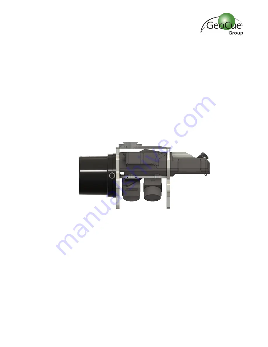
Страница 5: ...System POS the result is a true 3D imaging sensor 3DIS With its wide 120 fused field of view the True View 410 provides high efficiency 3D color mapping with vegetation penetration in a payload packag...
Страница 6: ...600 were purchased through GeoCue the antenna mounting plate and Ronin mount were installed by a GeoCue technician If you purchased your M600 from a third party you will need to install these componen...
Страница 7: ...8 3 2020 c Set Screw 4 Figure 3 Figure 3 d 50mm Spacer 4 Figure 4 Figure 4 e Hex Driver 1 5mm 2mm Figure 5 Figure 5 2 On the drone remove the 4 screws indicated below Figure 6 These screws will be use...
Страница 8: ...Figure 7 WARNING Do not overtighten If screws are too tight they will press into the plastic plate below and could cause the plate to crack Figure 7 4 Install the four 50mm spacers on top of the set...
Страница 9: ...ware User Guide 8 3 2020 Figure 10 6 Install the controller box on to the top plate with the LEDs facing out away from the center of the drone The controller box is designed to fit into the antenna mo...
Страница 10: ...the drone remove the 3 screws on each leg of the stock mount Figure 11 Keep the screws they will be used again Figure 11 2 On the Ronin Mount loosen the screws that hold the legs to the rails enough...
Страница 11: ...de 11 True View 410 Hardware User Guide 8 3 2020 Figure 13 4 Using the screws removed from the drone in Step 1 apply Loctite to each screw and install the mount with the red lever facing the back of t...
Страница 12: ...drone on a stable surface with the landing gear down 2 Turn the red lever Figure 15 on the Ronin mount until it is loose but do not remove it completely Figure 15 3 Align True View so that the batter...
Страница 13: ...ew is tightly locked in place 6 Loop the safety lanyard through the upper metal plate of the True View and around one of the bars of the payload mount and close the safety lanyard Figure 18 Figure 18...
Страница 14: ...ware User Guide 8 3 2020 Figure 19 8 Attach the CAT6 cable to the True View unit Figure 20 Figure 20 9 Attach the GNSS antenna cable to the True View unit Figure 20 and screw the antenna on to the ant...
Страница 15: ...True View 410 Hardware User Guide 15 True View 410 Hardware User Guide 8 3 2020 Figure 21...
Страница 16: ...standalone and does not use power from the aircraft s power system This ensures that True View does not interfere with critical flight functions You can expect to get about 90 minutes from each batte...
Страница 17: ...ge and is copied into the Cycle System folder upon creation of each Cycle The SCF contains information on the calibration parameters of all components for each True View system and is used by True Vie...
Страница 18: ...nsferred during wind down and they will have to be manually downloaded from each camera SD card and placed in the Camera 1 and Camera 2 folders in the cycle folder The image transfer process takes abo...
Страница 19: ...rcentage entered in the LowBatteryPercent and CriticalBatteryPercent fields The BAT light will be green if the battery is above the LowBatteryPercent value It is 50 by default The BAT light will be ye...
Страница 20: ...yDistance X Y and Z The SYS light will be flashing yellow when the aircraft lands Wait until the SYS light is solid yellow file transfer complete to power off the system If the system has not landed w...
Страница 21: ...410 Hardware User Guide 21 True View 410 Hardware User Guide 8 3 2020 If AutoDelete is false the user must manually delete data from the UMS or SD cards If storage space is full flight data will not...
Страница 22: ...both L1 and L2 signals and must be during the same time as the flight Single base is the only processing method if you plan to process with the local option selected 2 SmartBase SmartBase is a cloud...
Страница 23: ...ure 31 Insert True View Battery 2 Lift all antennas up and tighten the nut Figure 32 on the True View antenna Figure 32 True View Antenna 3 Place the drone in an open area where you intend to takeoff...
Страница 24: ...ser Guide 8 3 2020 5 Turn on the True View unit with the switch located in the battery compartment Figure 33 Figure 33 True View Power Switch 6 Close the battery compartment door and lock the latch 7...
Страница 25: ...mware version 2 0 3 When the system is powered on its position is recorded and this position is used as the home point for the system Once the sensor travels a specified distance 25 meters by default...
Страница 26: ...26 True View 410 Hardware User Guide 8 3 2020 Figure 35 shows all the lighting sequences and their meanings Figure 36 shows how to interpret the symbols in the table Figure 35 Controller Box LEDs Fig...
Страница 27: ...quickly stop 5 Wait 2 seconds then on the left stick turn the aircraft about 10 degrees and wait one second 6 Pull the right stick all the way back quickly and hold for 6 seconds The drone will quickl...
Страница 28: ...until the system LED changes from solid green to flashing yellow 2 The flashing yellow light indicates the True View is writing data to the USB drive Be sure not to power off the True View or remove t...
Страница 29: ...Advanced with the addition of the True View workflow tools It is limited to product areas of no more than 4 km2 of LIDAR data True View Evo Unlimited this is the same functionally as True View EVO bu...
Страница 30: ...t to the APX 15 CONFIGURE TRUE VIEW WI FI 1 Power on the True View 410 and wait for 30 seconds or until Trueview410 appears in your list of Wi Fi networks a If cannot find the network turn off the Tru...
Страница 31: ...i has been previously configured before attempting to connect to the APX 15 1 Power on the True View 410 and wait for 30 seconds 2 Connect to Trueview410 Wi Fi network a If the TrueView410 Wi Fi netwo...
Страница 32: ...User Guide 8 3 2020 DOWNLOAD T04 FILES 1 After you Log in to APX 15 on the left side menu select Data Logging Data Files Internal 2 Select the applicable T04 file s T04 files are named YYMMDDHHMM T04...
Страница 33: ...rcraft you will need to measure the offsets then log in and enter them into the APX 15 Figure 41 The position is referenced to the APX 15 which is enclosed inside of the housing and cannot be physical...
Страница 34: ...mounting plate Figure 42 where the cameras are attached The APX 15 is 1 644cm above this plate A tip for measuring Z is to install the True View and GNSS antenna on the aircraft and place it on a tabl...
Страница 35: ...ction of the heading of the aircraft If the antenna is forward of the APX 15 the X offset is positive If the antenna is behind the APX 15 the offset is negative The reference point is the rear aluminu...
Страница 36: ...ng of the aircraft If you are standing behind the aircraft looking in the direction of the heading the offset will be negative if the antenna is left of the centerline of the APX 15 The offset will be...
Страница 37: ...is secure and won t interfere with the props 17 Remove True View lens caps clean lenses sensor if necessary 18 Power on True View using main power button located just above the battery pack door must...
Страница 38: ...lashing yellow transferring data 33 Monitor the True View SYS LED flashing Yellow means data is being copied to USM solid Yellow data copy is complete Wait for solid Yellow 34 Power True View OFF usin...
Страница 39: ...issues with PPK processing and accuracy The base station should be configured to record at 1Hz Question What are the base station requirements for the True View 410 Answer The minimum requirement bas...
Страница 40: ...upport request is sent during business hours a representative will typically get back to you within 4 hours If received after hours a response will be sent the following day To speed response time ple...