28
Adjustment
?
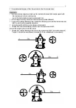
Remove the reticule cover between the eyepiece of
the telescope and the focusing knob.
?
Set up point D between point B and C. The distance of
DC should be a quarter of BC. Adjust the two
adjusting screws to move the reticule to have its cross
aim at point D.
?
Repeat above inspection and adjustment steps until B
and C are superposed.
?
Assemble back the reticule cover to its original
position.
?
Loosen one screw if the vertical hair of the crosshair
should be moved, then tighten the other one in the
same turn. Loosen the screw counterclockwise and tighten in the clockwise
direction. The turn should be as little as possible no matter loosen or tighten.
?
After the adjustment above, the zero reset of the vertical angle should be carried
out.
? Automatic compensation of the vertical axis
The instrument is equipped with the electronic incline sensor device, which can
compensate the vertical axis.
Check
? After mounting and leveling the instrument, coincide the point of the telescope
with the line between the center of the instrument and its any level screw. Then
tighten the horizontal braking knob.
? Set zero for indication of the vertical plate after power-on. Tighten the vertical
clamp knob and the instrument displays the current value of the vertical angle the
telescope pointed.
? Turn the footscrew in one direction till 10 mm or so (circle distance). The value of
vertical angle also changes correspondingly till it disappears and the symbol “
b”
is
shown, which means the incline of the instrument’
s axis has exceeded out of the
compensated range. When turning the leveling screw in reverse, the instrument
returns to display the vertical angle (repeat testing and observe the changes on the
critical point), which means the compensation device works well.
Adjustment
When the compensation doesn’
t work well or works abnormally, send to the factory
for repair.
Adjusting screw


