REV A
March 2007
Section 4 • Repair Procedures
4 - 108
GS-30 • GS-32 • GS-46
Part No. 97385
Non-steer End:
1 Chock the wheels at the steer end of the
machine.
2 With a suitable floor jack, lift the non-steer end
of the machine to a height that will allow the
outrigger cylinder to be removed.
3 Remove the fasteners securing the cover to the
rear outrigger enclosure. Set the fasteners to
the side and remove the cover.
4 Tag and disconnect the wire harness from the
outrigger cylinder solenoid valve and the
pressure transducer.
5 Tag and disconnect the pressure transducer
from the outrigger cylinder. Plug the fitting on
the cylinder.
6 Tag, disconnect and plug the hydraulic hoses
from the outrigger cylinder. Cap the fittings on
the cylinder.
Bodily injury hazard. Spraying
hydraulic oil can penetrate and
burn skin. Loosen hydraulic
connections very slowly to allow
the oil pressure to dissipate
gradually. Do not allow oil to squirt
or spray.
7 Support and secure the outrigger cylinder to a
suitable lifting device.
8 Remove the outrigger cylinder mounting
fasteners.
9 Remove the outrigger cylinder from the
machine.
Crushing hazard. The outrigger
cylinder may become unbalanced
and fall if not properly supported
when it is removed from the
machine.
Note: After installing a new cylinder or pressure
transducer, the pressure transducers on the
machine must be calibrated. Refer to Section 1-4,
How to Calibrate the Outrigger Pressure
Transducers.
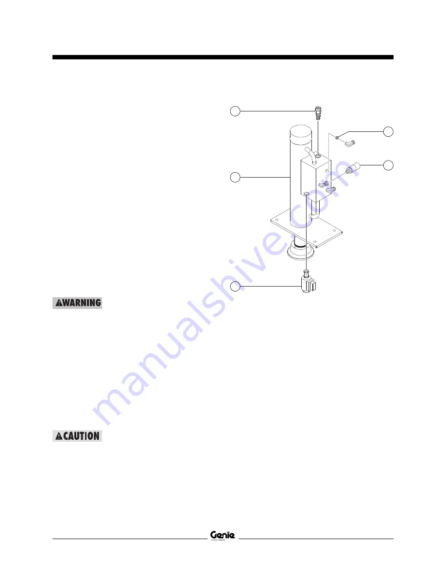
OUTRIGGER COMPONENTS
Non-steer End Outrigger
a
orifice
b
pressure transducer
c
valve coil
d
outrigger cylinder
e
check valve
c
e
CC and CD
CF
d
b
a
Extend
Retract
CE
Y33
Y34
CG
Содержание GS-1530
Страница 3: ...February 2012 Part No 97385 GS 30 GS 32 GS 46 iii INTRODUCTION Serial Number Legend ...
Страница 4: ...February 2012 GS 30 GS 32 GS 46 This page intentionally left blank iv ...
Страница 22: ...February 2009 Section 2 Specifications 2 8 GS 30 GS 32 GS 46 Part No 97385 This page intentionally left blank ...
Страница 187: ...Section 6 Schematics April 2008 Part No 97385 GS 30 GS 32 GS 46 6 13 This page intentionally left blank ...
Страница 191: ...Section 6 Schematics April 2008 Part No 97385 GS 30 GS 32 GS 46 6 17 This page intentionally left blank ...
Страница 195: ...Section 6 Schematics April 2008 Part No 97385 GS 30 GS 32 GS 46 6 21 This page intentionally left blank ...
Страница 207: ...Section 6 Schematics April 2008 Part No 97385 GS 30 GS 32 GS 46 6 33 This page intentionally left blank ...
Страница 211: ...Section 6 Schematics April 2008 Part No 97385 GS 30 GS 32 GS 46 6 37 This page intentionally left blank ...
Страница 215: ...Section 6 Schematics April 2008 Part No 97385 GS 30 GS 32 GS 46 6 41 This page intentionally left blank ...
Страница 231: ...Section 6 Schematics April 2008 Part No 97385 GS 30 GS 32 GS 46 6 57 This page intentionally left blank ...
Страница 235: ...Section 6 Schematics April 2008 Part No 97385 GS 30 GS 32 GS 46 6 61 This page intentionally left blank ...
Страница 239: ...Section 6 Schematics April 2008 Part No 97385 GS 30 GS 32 GS 46 6 65 This page intentionally left blank ...
Страница 243: ...Section 6 Schematics April 2008 Part No 97385 GS 30 GS 32 GS 46 6 69 This page intentionally left blank ...
Страница 247: ...Section 6 Schematics April 2008 Part No 97385 GS 30 GS 32 GS 46 6 73 This page intentionally left blank ...
Страница 263: ...Section 6 Schematics April 2008 Part No 97385 GS 30 GS 32 GS 46 6 89 This page intentionally left blank ...
Страница 267: ...Section 6 Schematics April 2008 Part No 97385 GS 30 GS 32 GS 46 6 93 This page intentionally left blank ...
Страница 271: ...Section 6 Schematics April 2008 Part No 97385 GS 30 GS 32 GS 46 6 97 This page intentionally left blank ...
Страница 275: ...Section 6 Schematics April 2008 Part No 97385 GS 30 GS 32 GS 46 6 101 This page intentionally left blank ...
Страница 296: ...Section 6 Schematics March 2007 6 122 GS 30 GS 32 GS 46 Part No 97385 ...
Страница 298: ......


