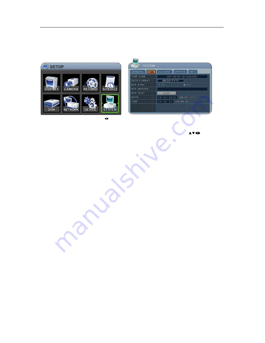
Genie GDVRH-604 Скачать руководство пользователя страница 67

69 


8.2. TIME   

Make sure to set up your Date and Time before starting to Record.   


1.  Use Left/Right buttons [

] to select on “Time” menu tab. The menus are displayed 

with options in the left-hand column and settings in the right hand column. A cursor 

(highlighted menu) can be moved using the directional buttons [

]. Press the   

[-, +]

 buttons to change the values. 


1) Time 

Zone

: Refer to <Appendix 1: Time Zone Chart> 

Selects the time zone where the DVR is located. Time Zone contains DST (Daylight 

Saving Time) ON. If you choose Time Zone with DST, there is no change in the 

system time stamp for recorded data. When the Daylight Saving End date and time 

occurs the DVR’s time goes back one hour.   

2) Date 

Format:

 Select Date display format.   

[ MM/DD/YYYY 

 DD/MM/YYYY 

 YYYY/MM/DD ]


3) NTP SYNC:

 The internal time of DVR can be synchronised with an external time 

source using NTP (Network Time Server) Configuration. If the NTP option is ON, the 

DATE and Time option is inactivate.   

4) NTP Server:

 Allows you to use a public or private NTP server. Enter the IP address 

of the server or domain. The default setting is public “pool.ntp.org”. 

<Note> Time Sync. Interval: Min 64 sec. Max 1024 sec.     

5) NTP 

TEST: 

Test whether NTP Server works or fails. 

6)  Date & Time: 

Set current time and date.


2.    Save changes and exit the menu, press the [MENU] button.   

Exit the menu without making changes, press the [CANCEL] button.


Содержание GDVRH-604

Страница 1: ...0 GDVRH Series DIGITAL VIDEO RECORDERS User Guide GDVRH 604 4 Channels GDVRH 608 8 Channels GDVRH 616 16 Channels...

Страница 2: ...ser to the presence of un insulated dangerous voltage within the product s enclosure that may be of sufficient magnitude to constitute a risk of electric shock to persons The exclamation point within...

Страница 3: ...n 16 2 2 Connection of N C Normally Close 17 3 PTZ and controller connection 18 3 1 Connecting the Speed Dome directly into DVR 18 3 2 Connecting Both Speed Dome and DVR via J box 18 3 3 Connecting Si...

Страница 4: ...ORD 38 3 1 Record General 39 3 2 Resolution Recording speed Setting 40 3 3 Continues Normal Recording 41 3 4 Event Recording 42 3 5 Continues Event Motion Alarm Recording 44 4 SCHEDULE 44 4 1 CHART Se...

Страница 5: ...9 1 Playback 79 2 Time Search 79 2 1 Multi Channel Playback 79 2 2 Preview Search Single Channel Playback 80 2 3 Event Record Search 81 2 4 Event Source Search 82 2 5 Motion Area Search Single Channel...

Страница 6: ...d by your equipment distributor should conduct internal inspections alterations and repairs Stop operating the equipment immediately if it emits smoke or noxious fumes Failure to do so may result in f...

Страница 7: ...posure may damage the batteries and lead to the leakage of corrosive liquids fire electrical shock explosion or serious injury Do not attempt to disassemble alter or apply heat to the batteries There...

Страница 8: ...nce This equipment has been tested and found to comply with the limits for a Class A digital device pursuant to part 15 of the FCC Rules These limits are designed to provide reasonable protection agai...

Страница 9: ...the unit contact the supplier immediately If the unit must be returned it must be shipped in the original packing box CONTENTS QUANTITY REMARK DIGITAL VIDEO RECORDER 1 UNIT CLIENT SOFTWARE CD 1 REMOTE...

Страница 10: ...to make channel camera selection to choose the day in schedule option and to enter alphabets to label each channel 4 BACKUP Press this button to begin making a backup copy of the hard drive If there i...

Страница 11: ...NTER CANCEL ENTER Press this button to enter the sub menu CANCEL Press this button to exit menu without saving Direction In Menu setup mode used to move the cursor In Zoom mode used to move the zoom a...

Страница 12: ...11 2 Rear Panel Connectors 4 Channel 8 Channel 16 Channel...

Страница 13: ...1 4 1 8 1 16 9 AUDIO Input connectors D SUB to RCA 4 8CH 1 8CH 16CH 1 8CH 9 16CH 10 AUDIO Output 1 connectors RCA 11 Composite Monitor Output BNC standard composite video output connector 12 VGA out c...

Страница 14: ...he proper DVR System ID through which to operate Press the ID button and then press the number button within two seconds to select the system ID of the DVR If you set the System ID to Zero you can con...

Страница 15: ...by mouse Connect a mouse via USB port before use If you click right button of your mouse in Live mode and Playback mode you will see following virtual controller This Virtual Keyboards operate similar...

Страница 16: ...15 II INSTALLATION CONNECTIONS 1 Camera Monitor Audio Alarm sensor and Power cord Audio Audio Input Output impedance 0 dB 10 k Ohm 300 ohm voltage range 1 Vpp 1 4 Vpp...

Страница 17: ...16 2 Alarm inputs and Alarm outs 2 1 Connection of N O Normally Open The maximum of Alarm output is 1A 30VDC 0 5A 125V AC Alarm Input AI 4ch 1 4 8ch 1 8 16ch 1 16 G GND...

Страница 18: ...17 2 2 Connection of N C Normally Close...

Страница 19: ...18 3 PTZ and controller connection 3 1 Connecting the Speed Dome directly into DVR 3 2 Connecting Both Speed Dome and DVR via J box...

Страница 20: ...19 3 3 Connecting Single User with 2 DVR Configuration Multiple PTZ cameras are connected by daisy chaining the camera connection Multiple Keyboards are connected by cascade connection...

Страница 21: ...indow 7 d 16MB Video Card e 10 100 1000 BaseT Ethernet Port f CAT 5 6 UTP Cable for LAN Crossover cable for direct connect to PC Disclaimer The connection and remote viewing of the DVR may not be succ...

Страница 22: ...21 III QUICK START PAGE ADMIN and the default password is 000000 The Default User ID admin and password to run the EMS software is 0...

Страница 23: ...ry first time the time and date are set as default to January 1 2009 Thursday 01 00 00 Before any other operation of the Digital Video Recorder it is important to setup the time and the date Please re...

Страница 24: ...es Recording 3 Black No Recording 2 Event Indicator 1 Indicate Alarm In terminal is triggered by an alarm sensor To appear Alarm window press UP button This button toggles between Shows or Hide the Al...

Страница 25: ...changed to blue color while it s doing backup 4 Indicate Login or Locking status 5 Indicate Audio Data is stored the selected time during playback and turn to blue color 6 It shows Number of Client w...

Страница 26: ...DISPLAY buttons to activate the multiscreen display It is changed the order as shown below among your choice of SPLIT MODE 2 To start Auto Sequence press DISPLAY buttons for 2 seconds to begin full s...

Страница 27: ...window with the one from a smaller one It is used on 6 7 8 9 10 13 16 split mode Press F2 button on the remote controller Mark will be displayed Press Numeric button you wish to switching display Pres...

Страница 28: ...the camera you wish to zoom 2 Then press the ZOOM button on IR Remote controller Zoom area box pops up as shown below x2 3 Move the box to the desired position using Direction buttons 4 Press CANCEL...

Страница 29: ...ll be changed from SPOT 1 2 3 4 A 1 2 Spot Cancel Press Spot buttons for 2 seconds or CANCEL button to exit Main Monitor If there is no input it will automatically exit into Main mode after 5 seconds...

Страница 30: ...er button 2 When the DVR is powered on it will start to scan DVR status 3 Live Viewing screen will appear after initialization about 50sec It can be delayed when you have defect HDD it will try to fix...

Страница 31: ...n color 4 Press ENTER button to select the menu and display Sub Menu Using the mouse double click 5 Use Left Right buttons to select on TAP menu Selected items changed into Orange color It is automati...

Страница 32: ...elect Board Line between cameras GRAY WHITE BLUE BLACK DARK GRAY BACKGROUND Select Background color on NO VIDEO status GRAY WHITE BLUE BLACK DARK GRAY OSD ALIGNMNET The main video output can be displa...

Страница 33: ...2 SPOT3 SPOT4 2 Dwell Time Select the interval that each camera or Multi screen mode is displayed in a rotation Use button to change 1 second 30 second 3 Mode Select the appropriate monitor display to...

Страница 34: ...ges press CANCEL button 4 Press Display button for 2 seconds to start Auto Switch cameras on Main Monitor Press Spot button then Display for 2 seconds to start auto switch cameras on Spot Monitor 1 3...

Страница 35: ...Video Adjustment To Configure Camera Settings 1 Select Camera number button to configure the desired camera 2 Select Category to TUNE ITEM DEFAULT ADJUSTMENT BRIGHTNESS 50 The brightness of each came...

Страница 36: ...re PTZ Setup 1 Select Camera number button to configure the desired camera 2 Press Enter to configure PTZ Setup The menus are displayed with options in the left hand column and settings in the right h...

Страница 37: ...title use the virtual keyboard or press the appropriate numeric button on the IR Remote or the front panel Virtual Keyboard via Mouse on IR Remote Controller or Front Panel To save changes and exit t...

Страница 38: ...10 2 Motion Grid The area property is highlighted and motion detection can now be observed in the view window By default it s set to OFF Select All Press Enter to select Clear All Press Enter to sele...

Страница 39: ...sired camera 2 Select Category for GRID 3 The Privacy Mask creates a masking rectangle of a selected size then positions it on the video image To define the Privacy Mask area do the following 1 On the...

Страница 40: ...DD is full 4 Auto Delete Allows you to configure when the DVR automatically deletes all data from HDD It leaves the data for a selected duration from the current time NONE 12HOURS 1DAY 6DAYS 1WEEK 4WE...

Страница 41: ...etting NTSC MODE PAL MODE This DVR records each camera individually and then multiplexes them You can individually set up resolution and recording speed for each channel D1 stands for NTSC 720 480 PAL...

Страница 42: ...recording are off The DVR records video data continuously over a 24 hour period Recording setup is for normal recording Different settings can be configured for each camera To copy the setting to anot...

Страница 43: ...Determine whether Alarm Motion Video Loss is used for EVENT recording on the DAY EVENT tab 1 Alarm Recording One Alarm input can be configured to one channel One camera channel can be assigned to mul...

Страница 44: ...cates multiple alarm sources are selected c Please refer to CAMERA menu for Motion setup Note There may be cases when the recorder s built in motion detection function does not operate properly due to...

Страница 45: ...Recording Continuous and Event recording can be set simultaneously The DVR records video continuously over a 24 hour period but if an Event occurs the recording speed and picture quality can be set to...

Страница 46: ...ART Setup The schedule chart shows a graphical representation of the defined record mode Night mode will be set by default However the schedules are only displayed if a corresponding schedule has been...

Страница 47: ...rting time or the same as the starting time b Save changes and exit the menu press the MENU button Exit the menu without making changes press the CANCEL button 4 Copying Schedule a A cursor highlighte...

Страница 48: ...or highlighted menu can be moved using the directional buttons 2 Select each day to configure press Enter or click the mouse button 3 Use the buttons to change the values Mode OFF Day Night No Rec Sun...

Страница 49: ...DD stored Recording data but not used in current DVR e Back Up Data HDD stored Back up data f Other Data Neither Back Up nor Recording Data including AVI file Note Disconnected Disks disappear from th...

Страница 50: ...HDD If RECORDING DISK s exist it does not work B The used HDD should be from same series It s does not work with different series C There should be no time duplication in the HDD Device ODD Media HDD...

Страница 51: ...ce Displays logical Master and Slave device in mirroring Upper device is the Master and the other is used for slave If the slave HDD reaches 100 synchronisation Master HDD can be removed as well 3 Sta...

Страница 52: ...formation has slight differences between depending on the HDD manufacturer We recommend changing the HDD if its status is in PRE FAIL NOTE Please refer to STATUS explanation Status Explanation GOOD GO...

Страница 53: ...settings are available 1 IP Address Enter the static IP address 2 Netmask Enter the IP address of the subnet mask 3 Gateway Enter the IP address for the internet gateway server 4 PRI DNS Server Verify...

Страница 54: ...e Choose between Dual or Optimised 1 Dual Streaming the video audio data with a specified quality it s independent of recording configuration Note Max Dual Stream for Network 2 Optimised Stream the vi...

Страница 55: ...llow or deny remote access requires you to enter a range of IP addresses as an IP address and mask Host List will be activated when you select deny or allowed 7 Auto Port FWD Select the ADD button to...

Страница 56: ...to select Using the mouse click the option to select mail server 1 Default Default it is provided by manufacturer Mail notification options and mail address settings are available 2 SMTP SMTP Configu...

Страница 57: ...or IP address To set server name use the virtual keyboard or press the appropriate numeric button on IR Remote or front panel 2 Port Define the port the SMTP server will communicate through By defaul...

Страница 58: ...lect DDNS ON or OFF The default is OFF Press the buttons to select Using the mouse click the option to select DDNS provider 1 Default Default it is provided by manufacturer We offer DDNS service for r...

Страница 59: ...omain Name Enter the name you set for the DDNS web configuration 2 User ID Enter your user ID 3 Password Enter your password 4 Update Test Click the Update Test button to confirm the connection A succ...

Страница 60: ...Telnet Port 23 and Post Office Protocol 3 POP3 Port 110 are used To solve the firewall problem and let a visitor into the network the user instructs the router to allow traffic to pass through on a gi...

Страница 61: ...d if you know your Static IP address use the IP address to configure the S W example http 124 137 23 72 6000 2 Description of Symbols Connected x Not able to connect There s some limitation depends on...

Страница 62: ...lution on the monitor connected to the DVR It might display no video if a VGA monitor is not able to support high resolution NOTE In order to connect HDMI and VGA output to use both monitors please se...

Страница 63: ...nu can be moved using the directional buttons 2 INPUT Change the input type Use the buttons to change the values 3 OUTPUT you can configure how the Relay Outputs are controlled automatic or manual 1 U...

Страница 64: ...eserved 4 Control Manual stops for relay output and buzzer 4 Buzzer 1 USE ON The Buzzer sounds if an alarm is triggered The buzzer sounds for the duration of the RECORD TIME This buzzer relates to Ala...

Страница 65: ...s detected 3 Inactive Select Camera position after the event duration expires 4 Event Edit Press enter to edit multiple events The menus are displayed with options in the left hand column and settings...

Страница 66: ...atever the DVR ID is 2 DVR Name Type a DVR name to distinguish its location when you have several DVR s on a Network 3 KEY TONE By default the DVR emits a beep every time a button is pressed Set the k...

Страница 67: ...orded data When the Daylight Saving End date and time occurs the DVR s time goes back one hour 2 Date Format Select Date display format MM DD YYYY DD MM YYYY YYYY MM DD 3 NTP SYNC The internal time of...

Страница 68: ...10 and then activate it by setting to ON a Name Length up to 10 characters b Characters A to Z numerals 0 to 9 2 Privilege Admin can define each user s Privilege such as PLAYBACK PTZ CONTROL BACKUP CO...

Страница 69: ...rd Enter the 6 characters for the new password and then re enter the same password under the COMFIRM section An asterisk is displayed for each character entered 2 Save changes and exit the menu press...

Страница 70: ...buttons to move to the Start button Press the button to find upgrade files If the DVR finds a valid upgrade file the update menu is activated 4 Press the buttons to find correct upgrade file Version...

Страница 71: ...The DVR issues a single beep if Micom update is included 8 5 INFO System information contains brief model information Mac Address and installed HDD status Press the info button on the remote control...

Страница 72: ...r the PTZ related operation 1 P T Z Menu 1 To activate the Pan Tilt Control select the full screen display of the camera you wish to control 2 Then press the P T Z FOCUS button A shortcut Menu box pop...

Страница 73: ...and control box is displayed like the picture shown below 3 Place the mouse cursor inside the rectangle boundary Move the mouse cursor while pressing the left mouse button in the direction you want to...

Страница 74: ...set position SPOT OUT on remote controller Move the PTZ into the desired location Press the Preset button Custom 1 illuminates Set the for the Preset location Press Enter to save and exit Go to preset...

Страница 75: ...re 4 programmable Tours Use the buttons to change the values Group 1 Group 2 Group 3 Group 4 3 There is sub menu of each Tour group The menus are displayed with options in the left hand column and set...

Страница 76: ...remote controller Auto Tilt REW on remote controller Power On OFF FF on remote controller 6 PTZ Camera Model PAN TILT ZOOM Camera List Model Name 3X Speed Preset Go to Tour A Pan A Tilt Pat Me Esc Ent...

Страница 77: ...playback the DVR may be played back in reverse paused speed search up to 16 times the normal speed or move through picture by picture 2 Time Search 2 1 Multi Channel Playback 1 Press the Time Search b...

Страница 78: ...e search table Day will be displayed 2 Choose the desired channel to review by pressing a numeric button 3 Use the button to navigate to the desired Day Hour Minute 5min Minute 30sec Use the button to...

Страница 79: ...fault the TIME SEARCH CHART displays CONTINUOUS recording Yellow and EVENT recording Red TIME SEARCH CHART displays different outcomes according to the SEARCH MODE below FIGURE 1 1 Press the Event Sel...

Страница 80: ...cording data for ALARM MOTION and VLOSS events previously triggered on the DVR 1 Press button to select Event Source in search mode And select the event source Alarm Motion Vloss which you want to sea...

Страница 81: ...search the recording data that has motion in a specific area on a certain channel 2 Press the button to select the channel you want to search 3 Select the motion area you want to search Select all gri...

Страница 82: ...84 3 Go to Search 1 Press the Time Search button for 2 second and the Time Input menu pops up 2 Set the date and time you wish to search 3 Press Enter or Menu to start searching...

Страница 83: ...Remote and the Log List Menu pops up as shown below 2 Use the Up Down buttons to the desired Time to playback Use the Left Right buttons to move to the NEXT page 3 Press the ENTER button to start play...

Страница 84: ...ote and the backup menu appears 3 Use the buttons to change device selection Rack CD DVD RW 4 Use the button to select a channel All channels are set by default 5 Select the data for BACKUP 1 ALL Data...

Страница 85: ...at playback is not performed while the DVR is in a backup session 10 When finished the CD icon will change to Grey and the media is ejected If there is not enough space on the media the DVR automatica...

Страница 86: ...in Window format to FAT32 or NTFS To backup as an AVI File set the file format to AVI using the button 1 3 Back up Range Setup Press the button to set backup start time and press the button to set th...

Страница 87: ...ress numeric buttons to define an FTP server Port Define the port that the FTP server will communicate through User ID Enter the user ID of FTP Server It only recognises lower case letters even though...

Страница 88: ...button to see the DVR Log List Press the back up button to save the log list to USB memory stick 1 Use the buttons to select a device 2 Select type of Log List from ALL SYSTEM NETWORK EVENT and VLOSS...

Страница 89: ...Split Mode 1 4 6 7 8 9 10 13 16 Recording Speed 120fps 720 x 480 NTSC 100fps 720 x 576 PAL 240fps 720 x 240 NTSC 200fps 720 x 288 PAL 480fps 360 x 240 NTSC 400fps 260 x 288 PAL Recording Mode Continu...

Страница 90: ...me Time Zone Selectable DST AUTO Time Synchronization Supported via NTP server Miscellaneous Controls Mouse IR Remote Front Key SMS EMS IE Firmware upgrade Via USB Power Consumption 50W Operation Temp...

Страница 91: ...DST GMT 06 30 Standard GMT 07 00 Standard Russia DST GMT 08 00 Standard Russia DST GMT 09 00 Standard Russia DST GMT 09 30 Standard Australia DST GMT 10 00 Standard Russia DST Australia DST GMT 11 00...

Страница 92: ...nvironment or human health from uncontrolled waste disposal please separate this from other types of wastes and recycle it responsibly to promote the sustainable reuse of material resources Household...

Страница 93: ...1 Memo...

Отзывы: