16
Booster Power Supply Manual
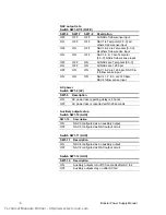
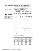
24 Vdc Notification Appliance Circuit (NAC) specifications
The NAC cable must be a minimum 18 gauge. Distance limits
are determined using the maximum allowable circuit resistance
and cable manufacturer's specifications. Restrictions apply when
calculating the wire size for the NACs:
1. Minimum supply voltage available is 18.9 V.
2. Minimum required circuit voltage at any NAC is 17 Vdc.
3. Maximum alarm current required for all NACs.
Using Ohm's law, the NAC current requirement, and a voltage
drop of 1.9 volts (18.9 - 17), the maximum allowable NAC
resistance is determined as follows:
V
drop
R
max
= Maximum allowable NAC resistance
R
max
= -------
I
max
= Maximum NAC current requirement
I
max
V
drop
= Maximum allowable voltage drop
from power supply to NAC
Using this formula, the maximum permissible circuit resistance
for a loaded (2.5 A) circuit is 0.76
9
as follows:
1.9 V
0.76
Ω
= -------
2.5 A
Using the Load vs. Distance table, the maximum allowable length
(D) of any listed wire gauge pair is determined as follows:
R
max
D = Distance in feet
D = ------- X 1000
R
max
=Maximum allowable wire resistance
R
/1000'PAIR
R
/1000' PAIR
= wire resistance per 1000' pair
Using this formula, the maximum length of a loaded (2.5 A) NAC
using a pair of 14 AWG wires is:
0.76
146.1' = ------- X 1000
5.2
146 feet is the maximum length of a loaded (2.5 A) NAC branch
circuit using a pair of 14 AWG wires.
Quick reference table (load vs. distance NAC circuit (1.9 volt drop))
Load
Maximum distance to last appliance, in feet (meters)
current
12 AWG
14 AWG
16 AWG
18 AWG
0.1 A
5,428 (1656)
3,654 (1114)
2,375 (724)
1,461 (446)
0.25 A
2,171 (662)
1,461 (446)
950 (290)
585 (178)
0.50 A
1,086 (331)
731 (223)
475 (145)
292 (89)
0.75 A
714 (218)
487 (148)
312 (95)
192 (58)
1.0 A
543 (165)
365 (111)
237 (72)
146 (44)
1.5 A
360 (110)
243 (74)
157 (48)
97 (29)
2.0 A
271 (83)
183 (56)
119 (36)
73 (22)
2.5 A
217 (66)
146 (44)
95 (29)
58 (18)
3.0 A
180 (55)
122 (37)
79 (24)
48 (15)
Typical cable pair resistances
Wire size
Resistance per
1,000 feet
12 AWG
3.5
Ω
14 AWG
5.2
Ω
16 AWG
8.0
Ω
18 AWG
13.0
Ω
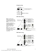
Note:
No "T" tapping
permitted.
Technical Manuals Online! - http://www.tech-man.com

