background image

Содержание 1543 Strobotac

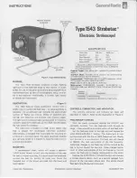
Страница 1: ...n 4J LS 6J LS Watt Seconds 0 6 0 16 Beam Candella2 30X106 4X10⁶ Beam Width3 11 11 1 Measured at peak intensity points 2 Measured with silicon photodetector 1 meter from lamp 3 Measured at Y intensity points External Trigger Std phone jack operated by contact closure device Sub Mult Mode Provides 0 1 accuracy by synchronizing to submultiples of the line frequency Environmental TEMPERATURE 0 to 50 C...

Страница 2: ...haft of a synchronous motor such as the Bodine Electric Co model no NSY 12 and make a single mark on the outer surface of the disc b Cover the flash rate dial of the strobotac with masking tape c Turn on the strobotac and the synchronous motor d Depress the NORMAL mode button and train the strobe light on the outer surface of the rotating disk e Turn the flash rate dial fully cw hignest flash rate...

Страница 3: ...ate determined by the frequency of the external trigger device such as a cam operated micro switch or a camera shutter Refer to the STROBES FOR PHOTOGRAPHERS para for an application of this mode NOTE The trigger device must be a contact closure with both sides isolated from ground If a contact device connected to the strobotac is operated at a frequency higher than 3780 fpm the strobe oscillator w...

Страница 4: ...lr de in the other retainer slot 4 d Rotate the screwdriver toward the reflector cover This action will pry the case outward and simultaneously bend the reflector cover slightly causing it to pop into place e Check to see that the side panels are properly seated and then tighten the case screws f Age the replacement lamp by operating the instru ment for a minimum of one hour KNOB AND DIAL REMOVAL ...

Страница 5: ...ssembly to remove the upper half refer to the KNOB AND DIAL REMOVAL procedure CLEANING CAUTION Unplug the stroboscope 3 minutes before cleaning PANEL Figure 5 Interior view showing the component side of the Control Board and the Power Supply Board TROUBLE ANALYSIS General Do not use an organic solvent Use a damp NOT WET cloth or sponge with a mild soap or detergent solution to clean the case refle...

Страница 6: ...n in the NORMAL mode If this mode functions correctly 02 is probably defective On EXTERNAL TRIGGER only Check to see that the external contact closure device is isolated from ground If so check the internal connections between A J 1 and the control board The next step should be to check 02 If this 6 PHONE 3 V TO 10 V BATTERY JACK 100 k n SCOPE lS U 1 transistor is not defective check the wiring to...

Страница 7: ...ing service instructions please write or phone our Service Department giving fu II information of the trouble and of steps taken to remedy it Be sure to mention the type number of the instrument Before returning an instrument to General Radio for service please contact our Service Department or nearest District Office requesting a Returned Material tag Use of this tag will ensure proper handling a...

Страница 8: ...omp 10 kQ 5 1 2 W 6100 3105 01121 RC20GF103J 5905 185 8510 R8 Comp 1 MQ 5 1 2 W 6100 5105 01121 RC20GF105J 5905 192 0390 R9 Comp 4 3 kQ 5 1 2 W 6100 2435 01121 RC20GF432J 5905 257 0935 R11 Comp 51 Q 5 1 2 W 6100 0515 01121 RC20GF510J 5905 279 3517 Rl3 Pot Comp P C 2 5 kQ 30 6049 0330 71450 X 201 Rl4 Comp 6 8 kQ 5 1 2 W 6100 2685 01121 RC20GF682J 5905 279 3503 Rl5 Comp 51 kQ 5 1 2 W 6100 3515 01121...

Страница 9: ...543 0700 8 ASM 1543 4700 Cl R23 Of RU OA Figure 9 Control circuit etched circuit diagram P N 1543 4700 RI S UOK R8 IM R 1 5 JL R9 4 31 L f l 1 14 8K 3 CONNECTIONS RIS 511 OUTPUT LEAVES SUBASSEMBLY INI UTFROMOIFFERENTSUBASSEMBLY OUTPUT REMAINS ON SUBASSEMBLY C INPUT FROM SAME SUBASSEMBLY Rl7 3301 l J ov r A Vf of r OUT 53 0 p l 5 IN 1 lOOK O FllOM Cb RD P 6 A C6 22p Lo FROMCV R Fi ECTOR ASM 1543 10...

Страница 10: ... 6100 5105 6110 3135 6110 0225 USE ISOLA IO N TRANS FOR M E R W HE N T t 5T INC T H I S NSTR UMG NT J3 3 J 3 6 llbAC R Z 51 2 W OlO LU 1 1 ossu eu ___ f IIW fii IIT Uif T QIITN1 11 11 1 010 SUftoSI IIIl 1 t o 1 f I UO U tlltkT Figure 10 Power supply circuit schematic diagram Fed Mfg Code Mfg Part No 90201 20 0000463441 01 00 24655 1543 0420 90201 20 000046339 01 00 90201 20 000046340 01 00 24655 1...

Страница 11: ... A Vl Strobotron NOTE Orientation Viewed from foil side Part number Refer to caption Symbolism Outlined area part gray ckt pattern if any parts side black other side Pins Square pad in ckt pattern collector 1 C pin 1 cathode of diode or end of capacitor ASSEMBLY PARTS LIST Fed GR Part No Mfg Code Mfg Part No Fed Stock No 4428 3116 72982 858 22 pF 20 4220 4154 00779 1 480426 0 4260 1031 82389 Nlll ...

Страница 12: ...0 NY 212 964 2722 New England Area 307 Evans Avenue Toronto 530 Ontario Telephone 416 252 3395 Montreal 514 737 2126 Maine Massachusetts New Hampshire Vermont Bolton Massachusetts 01740 Telephone 617 646 0550 CENTRAL REGIONAL CENTER Illinois Indiana Iowa Kansas Kentucky Michigan Minnesota Missouri Nebraska North Dakota Ohio South Dakota Western Pennsylvania Wisconsin 9440 West Foster Avenue Chicag...

Отзывы: