General Pump KE Series Скачать руководство пользователя страница 14

GENERAL PUMP

A member of the Interpump Group

KE SERIES

Page 14

The  new  roller  bearings  can  be  mounted  at  room

temperature with a press; it is necessary to hold them on 

the  side  surface  of  the  ring  nuts  with  suitable  rings. The

driving  operation  can  be  facilitated  by  heating  the  parts
at a temperature between 250-300oF, making sure that the

ring  nuts  are  correctly  fitted  in  their  seats.

Note:  Take  care  not  to  invert  the  components  of  the  2

bearings (outer ring nut of bearing 1 instead of the one of

bearing 2...).

To maintain the right axial load, the shim package has to

be calculated again as follows:

A) Install the crankshaft into the crankcase making sure

that the PTO end comes out on the correct side.

B) Fit  the  motor  side  flange  on  the  crankcase  with

special attention to the seal lip as indicated on point

11.1.2.

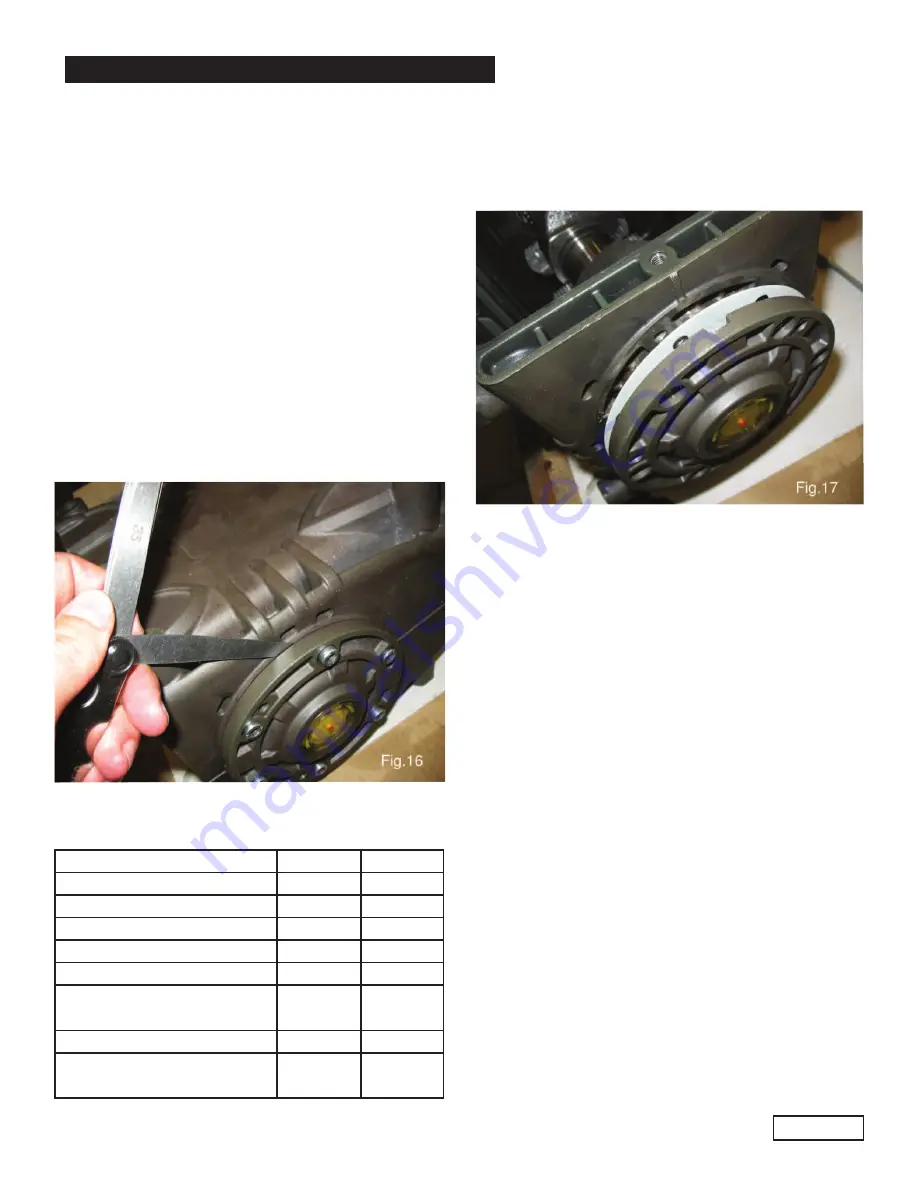
C) Position  the  sight  glass  side  flange  using  the  3 

screws  M6  x  16  until  the  crankshaft  cannot  be

turned freely by hand.

D) By  means  of  a  thickness  gauge  (see  Fig.  16) 

determine  the  shim  set  as  indicated  in  the  table 

below.

Measure

Shim Type # of Pieces

From: 0.05                  a: 0.10  
From: 1.00                  a: 0.20

0.1

1

From: 0.21                  a: 0.30

0.1

2

From: 0.31                  a: 0.35

0.25

1

From: 0.36                  a: 0.45

0.35

1

From: 0.46                  a: 0.55

0.35

0.10

1

1

From: 0.56                  a: 0.60

0.25

2

From: 0.61                  a: 0.70

1.35

0.25

1

1

E)

Fit  the  shims  under  the  sight  glass  cover

tightening  it  on  the  crankcase  with  the  screws,

checking that the stall torque is between 4 Nm and

6 Nm.

F)

If  the  torque  is  correct,  connect  the  rods  to  the

crankshaft,  otherwise,  calculate  the  shims  again

as per point “C”.

Ref 300614 Rev.E

05-12

Содержание KE Series

Страница 1: ...KE Owner s Manual Installation Use Maintenance 8 General Pump is a member of the Interpump Group Ref 300614 Rev E 05 12 ...

Страница 2: ... Page 6 7 3 Lowest operating RPM Page 6 8 CONNECTION AND PLUGS Page 6 9 PUMP INSTALLATION Page 7 9 1 Positioning Page 7 9 2 Direction of rotation Page 7 9 3 Water connections Page 7 9 4 Suction line Page 7 9 5 Filtration Page 8 9 6 Delivery time Page 8 9 7 Hose Diameters Page 9 10 START UP AND RUNNING PROCEDURES Page 10 10 1 Before start up Page 10 10 2 Starting up Page 10 11 MAINTENANCE INSTRUCTI...

Страница 3: ...argins during operation No precaution so far as is reasonably practical should be left out in the interest of safety both from the Manufacturer and the Operator 3 2 High pressure unit safety requirements 1 A safety valve should be installed in any delivery line and should be sized to discharge or by pass the entire pump flow rate 2 High pressure unit components with particular regard for those uni...

Страница 4: ... Operator for signs of difficulty or fatigue and watching the surrounding area for intrusion by other persons or unsafe situations If required he will shut off the pressure unit until it is safe to continue 4 The area in which the work is to proceed should be clear of loose items and debris to prevent tripping and slipping hazards 5 The water jet should be directed only and always against the work...

Страница 5: ...ial number should be specified when ordering spare parts Should the pump be modified i e by changing the original version than any change should be mentioned on the rating plate for future reference 5 TECHNICAL FEATURES 6 DIMENSIONS AND WEIGHT MODEL RPM FLOW RATE PRESSURE POWER GPM l min PSI Bar Hp kW KE20A 1450 8 3 31 4 4350 300 24 5 18 KE22A 1450 10 0 38 3625 250 24 7 18 16 KE24A 1450 11 9 45 2 ...

Страница 6: ...ring the pressure or volume of the pump above its maximum value 7 3 Lowest operating RPM The lowest operating speed of the crankshaft for all KE pumps all versions is 500 RPM 8 CONNECTIONS AND PLUGS KE pumps are provided with Fig 3 1 2 inlet ports IN Ø 1 NPT Suction line connection to either inlet port is acceptable the port not being used should be sealed with the correct plug 2 2 outlet ports OU...

Страница 7: ...rop in pressure due to the length and shape of the line 2 Should be as straight as possible minimizing changes in size and direction and positioned in such a way to allow air pockets and bubbles to escape 3 Should be perfectly airtight 4 Should be completely free from 90o elbows diameter reductions counter slopes T connections and should not be connected to other pipelines 5 Should positioned in s...

Страница 8: ...ltration degree and number of hours of each application 9 6 Delivery line For a correct delivery line comply with the following instructions 1 The first length of delivery hose should be flexible in order to isolate the pump vibrations from the rest of the system 2 Use only high pressure hoses and fittings able to guarantee the largest possible safety margins in any working conditions 3 A suitable...

Страница 9: ...cts the central scale indicating the diameters at a value of 80mm Example 2 With a flow of 70 l min and a water speed of 5 5 m sec the diagram line joining the 2 scales intersects the central scale indicating the diameters at a value of 16mm Optimal speeds suction 0 5 m sec delivery 5 m sec The diagram does not take into consideration the pipe and valve resistance drop in pressure due to the pipe ...

Страница 10: ...ig 7 and the oil sight glass 2 Fig 7 GENERAL PUMP A member of the Interpump Group KE SERIES Page 10 10 2 Starting up 1 When starting the pump up for the first time check for proper direction of rotation 2 Pump and motor engine must start offload set the regulating valve to zero or set the pressure line in dump mode by means of proper dumping devices 3 During operation check the rotating speed maki...

Страница 11: ...n any case the oil should be changed at least once a year since oxidation deteriorates it Recommended 50W oils Mineral or synthetic oils can be used but they must be chosen according to the working environment temperature Here below is a diagram indicating viscosity according to room temperature Oil grade SAE for engine oil Recommended according to the room temperature indicated in Co 5W 30 10W 40...

Страница 12: ...e seals into their seat thoroughly making sure they are correctly positioned B Introduce the units piston guide connecting rod into their seats to facilitate the tightening of the connecting rod cap position the connecting rod so you can easily read the number To install the crankshaft without key it is necessary to push the unit piston guide connecting rod backward C Before reassembling the side ...

Страница 13: ...k the rollers and races for wear if they are in good shape accurately clean the components with suitable degreaser and grease them again evenly with oil same as the pump oil The same shims can be used again taking care to fit them under the sight glass side cover After installing the complete unit glass sight side flange and crankshaft and motor side flange check that the rolling couple with conne...

Страница 14: ... comes out on the correct side B Fit the motor side flange on the crankcase with special attention to the seal lip as indicated on point 11 1 2 C Position the sight glass side flange using the 3 screws M6 x 16 until the crankshaft cannot be turned freely by hand D By means of a thickness gauge see Fig 16 determine the shim set as indicated in the table below Measure Shim Type of Pieces From 0 05 a...

Страница 15: ... end does not require periodical maintenance Service operations are limited to the component inspection and or replacement when necessary Valve Units A Loosen the valve cover screws B Extract the valve plugs with an extractor or a M8 threaded rod C Extract the valve unit with the same tool See Fig 18 Valve components of each valve unit are pressed together and therefore they can be easily replaced...

Страница 16: ... to carry out the replacement more easily apply a very small quantity of silicone grease on the pressure packing lips and their seats on the fluid end It is necessary to help the sealing lips settle on the plunger D Fit the fluid end back in place and tighten the bolts with a torque wrench set for the value indicated in the table on page 17 and in the sequence incicated here below 11 2 3 Plunger T...

Страница 17: ...lowing precautions should be taken after use drain the entire suction and delivery lines filter included by means of discharging devices provided and positioned specifically for this purpose along the lowest point of the lines run the pump only for a few seconds in order to drain the water collected inside the fluid end Or when applicable add a recommended amount of anti freeze into the water tank...

Страница 18: ...GENERAL PUMP A member of the Interpump Group KE SERIES Page 18 16 EXPLODED VIEW AND PARTS LIST Ref 300614 Rev E 05 12 ...

Страница 19: ... 78 3 31 F70080070 Packing retainer Ø 20 3 F70080170 Packing retainer Ø 22 3 F70080270 Packing retainer Ø 24 3 F70080370 Packing retainer Ø 28 3 F70080470 Racking retainer 3 Item Part Description QTY 32 F90268800 L P packing Ø 20 3 F90271300 L P packing Ø 22 3 F90273700 L P packing Ø 24 3 F90275000 L P packing Ø 28 3 F90276000 L P packing Ø 30 3 33 F70216070 Middle ring Ø 20 3 F70216170 Middle rin...

Страница 20: ... NOT DELIVER THE RATED VOLUME insufficient feeding due to the cause listed above RPM are less than rated excessive amount of water by passed by the pressure regulating valve worn out valves excessive leakage from pressure packings INSUFFICIENT PUMP PRESSURE the nozzle is or has become too large RPM are less than rated excessive leakage from pressure packings excessive amount of water by passed by ...

Страница 21: ...ried out with simple tools for mounting and dismounting the components but special tools can be made to facilitate the operations The drawings here below will help the operator make tools if he choosed to 18 1 Crankshaft oil seal assembling 18 2 Piston guide oil seal assembling Page 21 Ref 300614 Rev E 05 12 ...

Страница 22: ...v E 05 12 Page 22 19 MAINTENANCE LOG OIL CHANGE GREASE PACKING REPLACEMENT PLUNGER REPLACEMENT VALVE REPLACEMENT HOURS DATE GP Companies Inc 1174 Northland Drive Mendota Heights MN 55120 Phone 651 686 2199 Fax 800 535 1745 www generalpump com email sales gpcompanies com ...

Отзывы: