2.3
Mechanical Dimensions
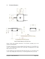
Figure 2 Mechanical dimensions of FPS-003, in mm
Figure 2 shows the mechanical dimensions of the FPS-003, including the size and
locations of mounting holes.
For bottom mounting (screws inserted upwards from the bottom), use 5 #4-40 UNC L1/4
screws. The mounting holes used are the 4 corner holes (2 through holes and 2 blind
holes) and one in the center.
For top mounting (screws inserted downwards from the top), use 3 #2-56 UNC L5/16
screws. The mounting holes used are the two corner through holes and the center hole.
Document #: GP-IN-FPS-003-10
Page 6 of 9


