12
FEED MOTOR SWITCH WITH SAFETY KEY
OFF
ON
REMOVE
TO LOCK
OFF
REMOVE
TO LOCK
OFF
SAFETY KEY*
ON
OFF
F
G
H
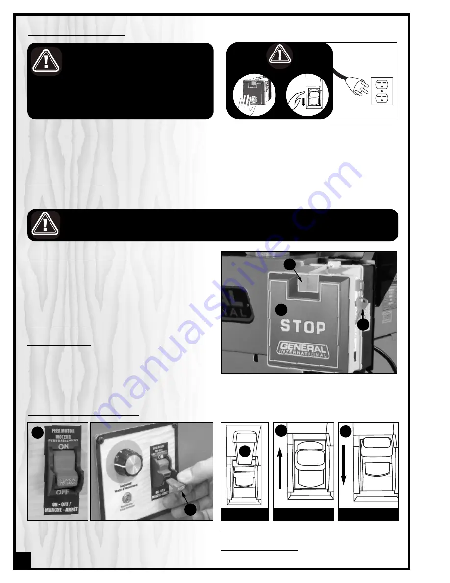
This model 30-120 M1 is also equiped with a simple ON /
OFF switch ,
D
, for the feed motor, featuring a removable
lock out safety key
E
.
To start the feed motor
: insert the safety key
F
and lift
the switch up,
G
.
To stop the feed motor
: push down on the switch
H
.
D
E
ON/OFF MAGNETIC POWER SWITCH
This model 30-120 M1 is equipped with a Magnetic 2-step
safety switch to prevent unwanted or unintentional
start-up and unauthorized use of the planer/molder.
The switch assembly is equipped with a GREEN “START” but-
ton
A
, an extra-large easy access RED stop panel
B
, and
a lock-out key
C
.
To start the molder
: Insert the lock-out key
C
and press on
the GREEN “START” button
A
.
To stop the molder
: Press on the RED “STOP” panel,
B
.
Once the RED “STOP” panel has been pressed, the plan-
er/molder can only be started by pressing once again on
the RED “STOP” panel to release the green button, then by
pressing on the green button.
B
A
C
ON/OFF POWER SWITCHES
This molder is equipped with 2 different ON/OFF power switches: one magnetic switch equipped with a lock-out key for
the drive motor and one independant on/off switch with a safety key and thermal /re-set breaker for the feed motor.
TO PREVENT UNAUTHORIZED USE OR UNINTENTIONAL START-UP, REMOVE THE SAFETY KEY AND LOCK-OUT KEY AND
STORE THEM IN A SAFE PLACE, OUT OF THE REACH OF CHILDREN, WHENEVER THE MOLDER IS NOT IN USE.
CONNECTING TO A POWER SOURCE
TO REDUCE THE RISK OF SHOCK OR FIRE DO
NOT OPERATE THE UNIT WITH A DA-MAGED
POWER CORD OR PLUG. REPLACE DAMAGED
CORD OR PLUG IMMEDIATELY.
TO AVOID UNEXPECTED OR UNINTENTIONAL
START-UP, MAKE SURE THAT BOTH OF THE
POWER SWITCHES ARE IN THE OFF POSITION
BEFORE CONNECTING TO A POWER SOURCE.
Once the assembly steps have been completed, uncoil the power cord and plug the power cord into an appropri-
ate outlet. Refer back to the section entitled “Electrical Requirements” and make sure all requirements and grounding
instructions are followed. When operations have been completed unplug the molder from the power source.
STOP
ON
REMOVE
TO LOCK
OFF
SWITCHES OFF
Содержание 30-120 M1
Страница 33: ...18 17 16 15 19 1 3 2 10 9 8 4 11 12 7 6 5 13 14 4 ELLIPTICAL JIG ASSEMBLY 33 ...
Страница 35: ...35 Notes ...


