


V7.x Packet Controllers
PCL Controller Overview
4-12
Xedge 6000 Hardware
032R440-000
Installation & Setup Guide
Issue 17
PCL Hardware Settings
Note
IMPORTANT ! Be aware that when S1 is set to F, all user configuration files and XOS code will be erased
from the card. This setting should be used with caution, and you must reset S1 back to 0, 4 or 8 immediately
after reboot to prevent inadvertent erasure with subsequent reboots.
Note
Additional S1 settings can be used to reboot the card to kernel for troubleshooting purposes, under the
guidance of your authorized Xedge field service representative.
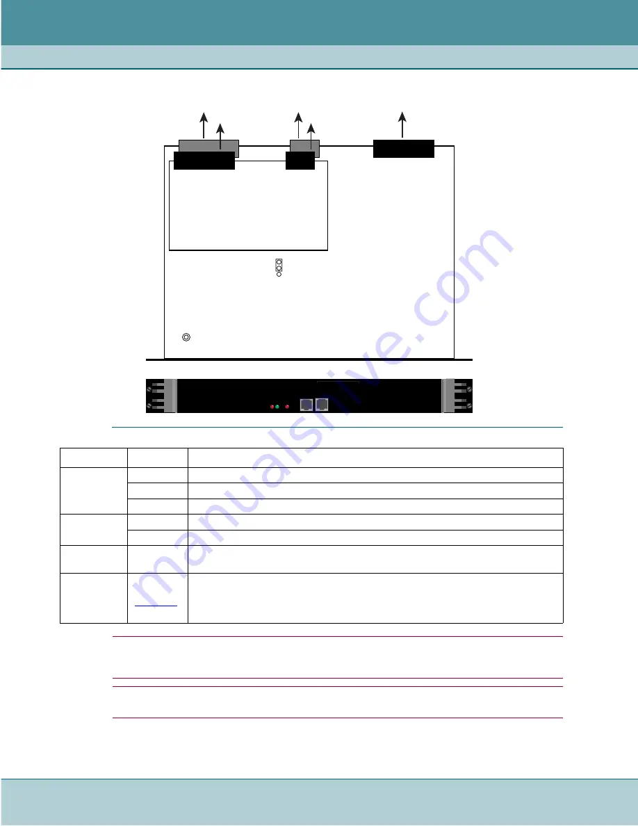
Table 4-4
PCL Controls and Indicators
Items
Designation Description
Front Panel
Status LEDs
FLT LED
FLT (red) is normally off; Lit when a problem prevents the Slot Controller from functioning.
RUN LED
RUN (green) illuminates when the Slot Controller is powered on and operating.
LNK FLT
LNK FLT (red) is not supported in this release.
Front Panel
Ports
MGMT
10/100 8-pin modular jack connects to Prosphere Server or ProSphere Server network.
USER
10/100 8-pin modular jack connects to Ethernet network.
On-board
Jumper
P3
Only for use in factory tests. For normal operation, this jumper must be set to
Pins 2 and 3, as shown above.
On-board
Rotary Switch
(16-position)
S1
(See
)
Set to 0 when PCL is in main slot 0 and slot 1 of Xedge 6160/6280.
Set to 0 when PCL is in standby slot 0 and slot 8 of Xedge 6640/6645.
Set to 8 when PCL is in non-slot 0 of any chassis (slot 0 must be a packet controller).
Set to F to delete all user-defined configuration files and XOS code (i.e. to factory default)
S1
P3
PCL Base Card
BACKPLANE
CONNECTORS
To Switch
Fabric
To
Backplane
3
1
PCL Front Panel
LPM-6
Daughter Card
To LIM1
FL
T
RU
N
LINK
FL
T
MGMT
USER
PCL
To LIM2


