background image

Operation

16

Owner’s Manual for 7.5 kW PowerPact™

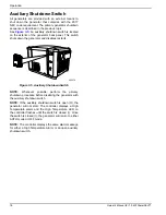
Auxiliary Shutdown Switch

All generators are provided with an external means to
shut down the generator that complies with the 2017
NEC code requirement. The primary generator shutdown
sequence is described in the previous topic.
See 

Figure 3-5

An auxiliary shutdown switch is located

on the exterior of the generator back panel. This switch
shuts down the generator and disables restarts. 

Figure 3-5. Auxiliary Shutdown Switch 

NOTE: 

Whenever possible, perform the primary

shutdown procedure before disabling the generator with
the auxiliary shutdown switch.

NOTE: 

If the auxiliary shutdown switch is open (O), the

generator will not start. The controller displays a High
Temperature alarm and the High Temperature LED on
the controller flashes until the switch is closed (I). Once
the switch is closed (I), the generator will return to either
AUTO mode or OFF mode.

NOTE: 

The controller displays the same alarm message

for either a High Temperature Alarm or an open auxiliary
shutdown switch.

005570

005570

Содержание PowerPact G0069981

Страница 1: ...uct support lookup Pour le français visiter http www generac com service support product support lookup Register your Generac product at WWW GENERAC COM 1 888 GENERAC 888 436 3722 000209b WARNING Loss of life This product is not intended to be used in a critical life support application Failure to adhere to this warning could result in death or serious injury ...

Страница 2: ...cement of parts are the responsibility of the owner operator and as such are not considered defects in materials or workmanship within the terms of the warranty Individual operating habits and usage may contribute to the need for additional maintenance or service When the generator requires servicing or repairs Generac recommends contacting an IASD for assistance Authorized service technicians are...

Страница 3: ...ansfer to Generator Power Source 13 Transfer Back to Utility Power Source 14 Automatic Transfer Operation 14 Automatic Sequence of Operation 15 Utility Failure 15 Cranking 15 Cold Smart Start 15 Load Transfer 15 Shutting Generator Down While Under Load Or During A Utility Outage 15 Auxiliary Shutdown Switch 16 Section 4 Maintenance Maintenance 17 Performing Scheduled Maintenance 17 Clearing a Main...

Страница 4: ...Table of Contents iv Owner s Manual for 50 Hz Air Cooled Generators This page intentionally left blank ...

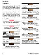
Страница 5: ...d incorrectly or carelessly Observe them carefully Their definitions are as follows NOTE Notes provide additional information important to a procedure or component These safety alerts cannot eliminate the hazards they indicate Observing safety precautions and strict compliance with the special instructions while performing the action or service are essential to preventing accidents The operator is...

Страница 6: ...e as an intermediate power supply in the event of temporary power outage only Doing so could result in death serious injury and equipment damage 000247a 000187 WARNING Electrocution Potentially lethal voltages are generated by this equipment Render the equipment safe before attempting repairs or maintenance Failure to do so could result in death or serious injury 000130 WARNING Accidental Start up...

Страница 7: ...turer s instructions Failure to do so could result in death or serious injury WARNING 000144 DANGER Electrocution Contact with bare wires terminals and connections while generator is running will result in death or serious injury 000150 DANGER Electrocution Never connect this unit to the electrical system of any building unless a licensed electrician has installed an approved transfer switch Failu...

Страница 8: ... 000100a WARNING Consult Manual Read and understand manual completely before using product Failure to completely understand manual and product could result in death or serious injury WARNING to use required safety equipment could result in death or serious injury 000257 Electrocution Refer to local codes and standards for safety equipment required when working with a live electrical system Failure...

Страница 9: ... G Fuel Connection Hole N Air Box B Controller Lid H Data Label O Spark Plug C Control Panel J Battery Access Panel P Exhaust Enclosure D Circuit Breaker K Oil Drain Hose Q Alternator E Customer Connection Box L Oil Fill Dipstick R Starter Motor F Auxiliary Engine Shutdown Switch M Front Panel not shown 005568 A B G F E C A H J K L M N O P Q R D ...

Страница 10: ...ese generators are rated in accordance with UL 2200 Safety Standard for Stationary Engine Generator Assemblies and CSA C22 2 No 100 04 Standard for Motors and Generators Natural Gas ratings will depend on specific fuel joules Btu content Typical derates are between 10 20 off the LP gas rating Circuits to be moved must be protected by same size breaker For example a 15 amp circuit in the main panel...

Страница 11: ...al number production date voltage frequency amps country of origin rated ambient temperature The model data decal also displays certification symbols by Underwriter s Laboratory UL and the Southwest Research Institute SwRI Fuel Inlet Pressure Displays the unit serial number along with the minimum and maximum inlet pressures for natural gas NG and liquid propane LP supply Space is provided for the ...

Страница 12: ...dual fuel carburetion system The unit will run on natural gas or LP gas vapor but it has been factory set to run on natural gas The fuel system will be configured for the available fuel source during installation Recommended fuels should have a BTU content of at least 1000 BTUs per cubic foot 37 26 megajoules per cubic meter for natural gas or at least 2500 BTUs per cubic foot 93 15 megajoules per...

Страница 13: ...he Wireless Local Monitor provides you with instant status without ever leaving the house Status lights red yellow and green alert owners when the generator needs attention Magnetic backing permits refrigerator mounting and gives a 600 foot 183 m line of sight communication Wi Fi LP Fuel Level Monitor G007005 0 The Wi Fi enabled LP fuel level monitor provides constant monitoring of the connected L...

Страница 14: ...General Information 10 Owner s Manual for 7 5 kW PowerPact This page intentionally left blank ...

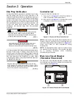
Страница 15: ...nd out sightly to unlock then lower to close Figure 3 1 Open and Close Controller Lid NOTE Local codes may require this compartment to be locked A hasp is provided so the owner operator can secure the compartment with a padlock C in Figure 3 1 Check local codes for side compartment locking requirements NOTE All appropriate panels must be in place during any operation of the generator This includes...

Страница 16: ...LED will flash 001052 A B C Button Description of Operation AUTO GREEN Selecting this button activates fully automatic system operation It also allows the unit to automatically start and exercise the engine every seven days with the setting of the exercise timer see Setting the Exercise Timer MANUAL BLUE This button will crank and start the generator Transfer to standby power will not occur unless...

Страница 17: ... The exercise timer does not correct for daylight savings time NOTE The exerciser will only work in the AUTO mode and will default to exercise weekly at the time the Control Panel was last powered ON unless this procedure is performed The exercise function will need to be reset every time the 12 volt battery and T1 power to the generator are disconnected and then reconnected or when the fuse is re...

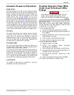
Страница 18: ...ility power source 2 Verify that normal UTILITY power source voltage is available to transfer switch terminal lugs N1 and N2 3 Press the AUTO button on the control panel interface 4 Set the main circuit breaker Generator Disconnect to the ON Closed position With these steps complete the generator will start automatically when utility source voltage drops below a preset level After the unit starts ...

Страница 19: ...TO mode if the ambient temperature is below a fixed temperature based on model the generator will warm up for 30 seconds This allows the engine to warm before a load is applied If the ambient temperature is at or above the fixed temperature the generator will start up with the normal warm up delay of six seconds Load Transfer The transfer of load when the generator is running is dependent upon the...

Страница 20: ... disables restarts Figure 3 5 Auxiliary Shutdown Switch NOTE Whenever possible perform the primary shutdown procedure before disabling the generator with the auxiliary shutdown switch NOTE If the auxiliary shutdown switch is open O the generator will not start The controller displays a High Temperature alarm and the High Temperature LED on the controller flashes until the switch is closed I Once t...

Страница 21: ...y to be valid Emissions critical maintenance consists of servicing the air filter and spark plugs in accordance with the Service Schedule The Control Panel will prompt for break in or regular maintenance when it is required to be performed Break in maintenance consists of the oil change valve clearance and tune up Regular maintenance includes the oil tune up air cleaner spark plug and valve cleara...

Страница 22: ...ug X X 6 M or 100 hours inspect 1 Y or 300 hours change Valve clearance X 1 Y or 300 hours General condition Vibration noise leakage X M Contact the nearest Independent Authorized Service Dealer for assistance if necessary Contact the nearest Independent Authorized Service Dealer for assistance if necessary Change oil after the first 20 hours of operation or 1 month Continue to check at intervals ...

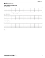
Страница 23: ...Owner s Manual for 7 5 kW PowerPact 19 Maintenance Log Battery inspection and charge check Dates Performed Oil oil filter air filter and spark plug replacement Dates Performed Valve Adjustment Dates Performed Notes ...

Страница 24: ... Turn ON the needed loads in the residence Engine Oil Recommendations To maintain the product warranty the engine oil should be serviced in accordance with the recommendations of this manual For your convenience Generac Maintenance Kits are available that include engine oil oil filter air filter spark plug s a shop towel and funnel These kits can be obtained from an IASD All Generac Maintenance ki...

Страница 25: ...lip 9 Refill the engine with the proper recommended oil For recommended oil see Figure 4 2 10 Connect the battery secure the battery access panel insert the fuse and switch the unit to MANUAL 11 Start the engine run for one minute and check for leaks 12 Shutdown the engine and check the oil level Add oil as needed DO NOT OVERFILL 13 Insert dipstick fill cap and hand tighten 14 Press the Control Pa...

Страница 26: ...the engine Figure 4 6 Valve Clearance Adjustment Check Valve Clearance 1 The engine should be cool before checking Adjustment is not needed if valve clearance is within the specification in Section 2 Specifications 2 Turn the generator OFF 3 Remove enclosure lid fasteners and lid Then remove the back panel 4 Remove spark plug wire and position wire away from plug 5 Remove spark plug 6 Make sure th...

Страница 27: ... Remove the 7 5 Amp fuse from the generator control panel Remove all jewelry watches rings metal objects etc Use tools with insulated handles Wear rubber gloves and boots Do not place tools or metallic objects on top of the battery Disconnect the charging source by pulling T1 fuse in the transfer switch prior to connecting or disconnecting battery terminals Wear full eye protection and protective ...

Страница 28: ...ntrol panel 6 Disconnect the battery cables Remove negative cable first 7 Remove battery charger AC input T1 Neutral cable has white sleeve at controller 8 While the engine is still warm drain the oil completely and then refill the crankcase with oil 9 Attach a tag to the engine indicating the viscosity and classification of the new oil in the crankcase 10 Remove the spark plug s and spray a foggi...

Страница 29: ...e incorrect 4 Fuel selector in wrong position 1 Check replace air cleaner 2 Clean re gap or replace plug s 3 Confirm fuel pressure to regulator is 10 12 in water column 19 22 mm mercury for LP and 5 7 in water column 9 13 mm mercury for natural gas 4 Turn fuel conversion valve to correct position Generator is set to OFF but the engine continues to run 1 Controller wired incorrectly 2 Defective con...

Страница 30: ...Troubleshooting 26 Owner s Manual for 7 5 kW PowerPact This page intentionally left blank ...

Страница 31: ...TIVATED Unit will not start in AUTO with utility loss Observe if all six Alarm and Warning LEDs are blinking simultaneously Refer to Generator Activation in the Installation Manual LOW OIL PRESSURE Unit will not start in AUTO with utility loss Check the Controller for alarms Check oil level add oil per Owners Manual If oil level is correct contact an IASD OVERCRANK Unit will not start in AUTO with...

Страница 32: ...ance due LED illuminates None Perform scheduled maintenance Clear Maintenance Due light NONE Utility present Generator running Active mode LED AUTO MANUAL OFF is flashing Check utility sense lines utility disconnect Contact IASD Close utility disconnect Table 6 1 System Diagnosis Continued Active Alarm Problem Things to Check Solution ...

Страница 33: ...Quick Reference Guide Owner s Manual for 7 5 kW PowerPact 29 This page intentionally left blank ...

Страница 34: ...Quick Reference Guide 30 Owner s Manual for 7 5 kW PowerPact This page intentionally left blank ...

Страница 35: ......

Страница 36: ...rights reserved Specifications are subject to change without notice No reproduction allowed in any form without prior written consent from Generac Power Systems Inc Generac Power Systems Inc S45 W29290 Hwy 59 Waukesha WI 53189 1 888 GENERAC 1 888 436 3722 www generac com ...

Отзывы: