Generac
®
Power Systems, Inc.
11
20-light Remote Annunciator
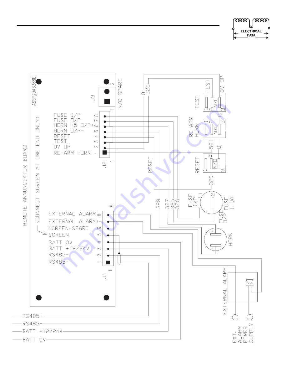
Wiring Diagram - Drawing No. 0E5617
Страница 1: ... STOP HIGH WATER TEMP LOW WATER LEVEL HIGH BATTERY VOLTAGE LOW OIL PRESSURE LOW WATER TEMP LOW FUEL HIGH WATER TEMP LOW OIL PRESSURE PRE ALARMS 1 AMP RESET ALARM RE ARM HORN TEST ON OFF OFF ON REMOTE START 0A6733 Surface Mount Models Flush Mount Models 004996 0 004997 0 Standard Annunciator 004998 0 004999 0 Annunciator w Remote Relay Panel PM DCP 20 light Remote Annunciator Owner s Manual ...
Страница 2: ...E WITH OTHER EQUIPMENT Alarm Relay Output 1 pair N O Volt free contacts 100mA 24V DC AGENCY COMPLIANCE NFPA 110 Yes NFPA 99 Yes TRANSPORTATION AND STORAGE Temperature 20 C to 80 C Humidity 0 95 Non Condensing Detailed Specifications 2 Environmental Specifications 2 Power Supply Requirements 2 Communication With Generator Control System 2 Interface With Other Equipment 2 Agency Compliance 2 Transpo...
Страница 3: ...n an existing sheet metal panel by using the four mounting holes in its front panel For wall mounting use a square outlet box behind the annunciator panel Flush Mounting Dimensions The Remote Annunciator panels Models 004996 0 and 004998 0 are mounted using any combination of the mounting holes in the back panel of the box itself Surface Mount Dimensions SYSTEM SPECIFICATION The 20 light remote an...
Страница 4: ...bove lights to light and alarm to sound WARNING INDICATORS These lights will flash when any alarm occurs and the horn will sound according to the following table These alarms will be latched not latched by the RAP according to the above table They can be acknowledged at the RAP using the Reset switch the active lamps will then stop flashing and remain in the ON state until the alarm signal clears ...
Страница 5: ...ether the load is pow ered by the utility For a non paralleling engine controller PM GC WITHOUT internal transfer switch it represents the status of the input 3 TB2 4 to the generator DCP This should be connected to the utility side auxiliary contact of the external transfer switch A closure to ground will cause the light to turn ON This shows whether the load is power by the utility For an engine...
Страница 6: ...N steady condition or OFF for normally on lights If the alarm no longer exists and it has also been latched OFF at the generator control panel pre alarm indicators only the active light will go OFF It will also silence the horn and re arm it for new alarm occurrences NOTE Pre alarm conditions MUST be reset at the generator set control panel RELAY OUTPUT The RAP will also provide a pair of Normally...
Страница 7: ... is being sent or received via the Tx and Rx check boxes Go to pull down menu for diagnostics and select Com Ports Select the port the R A is connect ed to normally port 0 and look to see if the check boxes change state If not data is not being transmitted received check the cabling If data is being received check the baud rate etc The Communication OK 1 Does the RS485 communications cable meet sp...
Страница 8: ...8 Generac Power Systems Inc 20 light Remote Annunciator ...
Страница 9: ...ROL SYSTEM THE GENERATOR CONNECT TO RS485 RS485 SCREEN OV 4 3 2 1 8 7 5 6 3 2 1 J2 1 326 325 327 328 RESET HORN 5 O P FUSE O P HORN O P RESET FUSE I P 7 6 8 5 4 J3 N C SPARE 520 0 EXTERNAL ALARM EXT ON THIS END ONLY CONNECT THE SCREEN POWER ALARM SUPPLY 1 0A FUSE FUSE I P HORN FUSE E O P 2 RESET 1 1 2 329 3 521 0 TEST TEST HORN RE ARM 1 1 3 3 2 2 0 0V OP 8 20 light Remote Annunciator Wiring Diagra...
Страница 10: ...10 Generac Power Systems Inc 20 light Remote Annunciator Wiring Diagram Drawing No 0E5617 ...
Страница 11: ...Generac Power Systems Inc 11 20 light Remote Annunciator Wiring Diagram Drawing No 0E5617 ...
Страница 12: ... FUSE 1A X AGC1 13 061286 1 SOUNALERT BUZZER 14 065511 1 PLUG PANEL PLASTIC 1 2 16 056892 4 SCREW CRIMPTITE 10 24 X 3 8 17 025034 2 PLUG STEEL 1 0625 18 0E5620 1 HARNESS 10 WIRE REMOTE ANN 19 022985 4 WASHER FLAT 6 ZINC 20 022155 4 WASHER LOCK 6 21 022188 4 NUT HEX 6 32 STEEL 22 0F0168 1 DECAL MODEL NO 04996 0 23 0D4462 1 DECAL WIRING REMOTE ANNUNCIATOR 3 2 6 5 2 0 0 5 21 0 0 18 J 10 14 10 B 2 A 1...
Страница 13: ...1 HOLDER FUSE 12 044299 1 FUSE 1A X AGC1 13 061286 1 SOUNALERT BUZZER 14 065511 1 PLUG PANEL PLASTIC 1 2 16 036918 4 SCREW PPHM 8 32 X 1 2 17 025034 1 PLUG STEEL 1 0625 18 0E5620 1 HARNESS 10 WIRE REMOTE ANN 19 022985 4 WASHER FLAT 6 ZINC 20 022155 4 WASHER LOCK 6 21 022188 4 NUT HEX 6 32 STEEL 22 0F0172 1 DECAL MODEL NO 04997 0 23 0D4462 1 DECAL WIRING REMOTE ANNUNCIATOR VIEW A A VIEW B B OTHER S...
Страница 14: ... AGC1 13 061286 1 SOUNALERT BUZZER 14 065511 1 PLUG PANEL PLASTIC 1 2 16 056892 4 SCREW CRIMPTITE 10 24 X 3 8 17 025034 2 PLUG STEEL 1 0625 18 0E5620 1 HARNESS 10 WIRE REMOTE ANN 19 022985 8 WASHER FLAT 6 ZINC 20 022155 8 WASHER LOCK 6 21 022188 8 NUT HEX 6 32 STEEL 22 0F0174 1 DECAL MODEL NO 04998 0 23 0D4461 1 DECAL WIRING REMOTE RELAY PNL 24 0D4462 1 DECAL WIRING REMOTE ANNUNCIATOR 3 2 6 0 5 21...
Страница 15: ...ER FUSE 12 044299 1 FUSE 1A X AGC1 13 061286 1 SOUNALERT BUZZER 14 065511 1 PLUG PANEL PLASTIC 1 2 16 036918 4 SCREW PPHM 8 32 X 1 2 17 025034 1 PLUG STEEL 1 0625 18 0E5620 1 HARNESS 10 WIRE REMOTE ANN 19 022985 8 WASHER FLAT 6 ZINC 20 022155 8 WASHER LOCK 6 21 022188 8 NUT HEX 6 32 STEEL 22 0F0176 1 DECAL MODEL NO 04999 0 23 0D4461 1 DECAL WIRING REMOTE RELAY PNL 24 0D4462 1 DECAL WIRING REMOTE A...
Страница 16: ...GENERAC POWER SYSTEMS INC P O BOX 8 WAUKESHA WI 53187 PH 414 544 4811 FAX 414 544 4851 Part No 0F0270 Revision 0 03 29 04 Printed in U S A ...