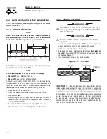
background image

3.6 ADJUSTING 

VALVE 

CLEARANCE

After the first 50 hours of operation, check the valve clearance in 
the engine and adjust if necessary.

Important: 

If feeling uncomfortable about doing this procedure or the 

proper tools are not available, please take the generator to the nearest 
service center to have the valve clearance adjusted. This is a very 
important step to insure longest life for the engine.

To check valve clearance:

Make sure the engine is at room temperature (60° - 80° F).
Make sure that the spark plug wire is removed from the spark plug 

and out of the way.

Remove the four screws attaching the valve cover.
Make sure the piston is at Top Dead Center (TDC) of its 

compression stroke (both valves closed). To get the piston at 
TDC, remove the intake screen at the front of the engine to gain 
access to the flywheel nut. Use a large socket and socket wrench 
to rotate the nut and hence the engine in a clockwise direction 
while watching the piston through the spark plug hole. The piston 
should move up and down. The piston is at TDC when it is up as 
high as it can go.

Insert a 0.002 - 0.004 inch (0.05 - 0.1mm) feeler gauge between 

the rocker arm and valve stem. Correct clearance is when a slight 
drag is felt when sliding the gauge back and forth. If the clearance 
is either excessively loose or tight the rocker arms will need 
adjusting.

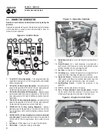
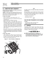
To adjust valve clearance:

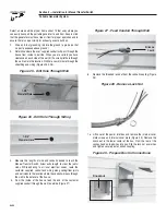
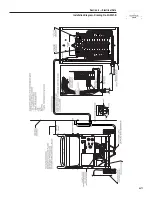
Loosen the rocker jam nut (Figure 21). Use an 10mm allen wrench 

to turn the pivot ball stud while checking clearance between 
the rocker arm and the valve stem with a feeler gauge. Correct 
clearance is 0.002-0.004 inch (0.05-0.1 mm).

Figure 21 - Valve Clearance Adjustment


NOTE:

The rocker arm jam nut must be held in place as the pivot ball 
stud is turned.

When valve clearance is correct, hold the pivot ball stud in place with 
the allen wrench and tighten the rocker arm jam nut. Tighten the jam 
nut to 174 in/lbs. torque. After tightening the jam nut, recheck valve 
clearance to make sure it did not change.

Install new valve cover gasket.
Re-attach the valve cover.

NOTE:

Start all four screws before tightening or it will not be possible 
to get all the screws in place. Make sure the valve cover gasket 
is in place.

Re-attach the spark plug wire to the spark plug.
Repeat the process for the other cylinder.

3.7 GENERAL

The generator should be started at least once every seven days 
and be allowed to run at least 30 minutes. If this cannot be done 
and the unit must be stored for more than 30 days, use the following 
information as a guide to prepare it for storage.

DANGER

  NEVER store engine with fuel in tank indoors or in 

enclosed, poorly ventilated areas where fumes may reach 
an open flame, spark or pilot light as on a furnace, water 
heater, clothes dryer or other gas appliance.


Section 3 — Maintenance

Portable Generator System

16

Содержание Guardian ULTRA SOURCE 004583-0

Страница 1: ...OOTING ELECTRICAL DATA PARTS WARRANTY 1 800 333 1322 ULTRA SOURCE Portable Generator COMMERCIAL INDUSTRIAL RESIDENTIAL MODEL 004583 0 17 500 Watt Portable Generator and 60 amp manual transfer switch w...

Страница 2: ...ystem 12 2 11 1 Initial Start up 12 2 11 2 Sensing Low Oil Pressure 12 2 11 3 Restarting 12 2 12 Charging a Battery 12 Section 3 Maintenance 13 3 1 Maintenance Schedule 13 3 2 Product Specifications 1...

Страница 3: ...Always disconnect spark plug wires and place the wires where they cannot contact the spark plugs to prevent accidental starting when setting up transporting adjusting or making repairs to the generat...

Страница 4: ...of the generator are rotating and or hot during operation Exercise care near running generators GENERAL HAZARDS Never operate in an enclosed area or indoors For safety reasons the manufacturer recomme...

Страница 5: ...rictly to local state and national electrical and building codes Comply with regulations the Occupational Safety and Health Administration OSHA has established Also ensure that the generator is operat...

Страница 6: ...is not intended for over the road use Refer to Figure 2 and install the wheel kit as follows Place the generator on a hard flat surface Stand at the engine end of the unit and gently tilt the generato...

Страница 7: ...e stator Connect the RED battery cable to the battery Positive terminal After making sure that the connection is tight slip the rubber boot over the terminal connection Connect the BLACK battery cable...

Страница 8: ...Volt AC 30 Amp single phase 60 Hz electrical lighting appliance tool and motor loads 6 120 240 Volt AC 50 Amp Receptacle Located on underside of control panel Supplies electrical power for the operat...

Страница 9: ...nce can cause a ground fault A GFCI receptacle does NOT protect against circuit overloads short circuits or shocks For example electric shock can still occur if a person touches charged electrical wir...

Страница 10: ...o recharge a battery Figure 11 12 Volt DC 10 Amp Receptacle 2 2 6 120 240 VAC 50 AMP RECEPTACLE Use a NEMA 14 50 plug with this receptacle Connect a 4 wire cord set rated for 250 Volts AC at 50 Amps t...

Страница 11: ...This surge of power lasts only a few seconds when starting such motors Make sure to allow for high starting wattage when selecting electrical devices to connect to the generator 1 Figure the watts ne...

Страница 12: ...evel DO NOT OVERFILL Install dipstick Install oil fill cap and finger tighten securely Check engine oil level before starting each time thereafter 2 6 2 ADDING GASOLINE Never fill fuel tank indoors Ne...

Страница 13: ...the Run position If engine falters move choke knob back out to 1 2 Choke position until the engine runs smoothly and then to Run position NOTE If engine fires but does not continue to run move choke...

Страница 14: ...An explosive mixture will remain around the battery for a long time after it has been charged The slightest spark can ignite the hydrogen and cause an explosion Such an explosion can shatter the batte...

Страница 15: ...s 1 6 gallons per hour Consumption 1 2 Load 3 1 MAINTENANCE SCHEDULE Follow the calendar intervals More frequent service is required when operating in adverse conditions noted below 3 2 PRODUCT SPECIF...

Страница 16: ...3 3 2 TO CLEAN THE GENERATOR Use a damp cloth to wipe exterior surfaces clean A soft bristle brush may be used to loosen caked on dirt oil etc A vacuum cleaner may be used to pick up loose dirt and de...

Страница 17: ...then remove foam pre filter service if necessary and remove paper filter Clean paper filter by tapping it gently on a solid surface If the filter is too dirty replace it with a new one Dispose of the...

Страница 18: ...ight the rocker arms will need adjusting To adjust valve clearance Loosen the rocker jam nut Figure 21 Use an 10mm allen wrench to turn the pivot ball stud while checking clearance between the rocker...

Страница 19: ...g hole with rag Press the Start button and allow engine to crank for 2 seconds Then press the Stop button Avoid spray from spark plug holes when cranking engine Install and tighten spark plugs Do not...

Страница 20: ...line 7 Overchoking 8 Low oil level 9 Excessive rich fuel mixture 10 Intake valve stuck open or closed 11 Engine has lost compression 1 Clean or replace air cleaner 2 Fill fuel tank 3 Drain fuel tank a...

Страница 21: ...ibution panel Ground rod 8 foot with grounding strap No 10 AWG stranded copper Padlock To lock external connection box after installation is complete Silicone caulk Fasteners to mount transfer switch...

Страница 22: ...sfer Switch Allow extra length to clear the joists studs While adhering to all local electrical codes route the customer supplied conduit and wiring along ceiling floor joists and wall studs to the lo...

Страница 23: ...tch and mark the mounting holes Drill the appropriate size pilot holes Mount the manual transfer switch to mounting surface with appropriate fasteners Figure 32 Mount Manual Transfer Switch DANGER Alt...

Страница 24: ...ire from the emergency circuit breaker from load center in the transfer switch All circuit wires are color coded and labeled for easy identification Repeat this process with remaining circuits to be p...

Страница 25: ...ol panel and is locked in place by the supplied spring retainer NOTE The power inlet box must be locked to ensure safety and to discourage tampering 33HP 990cc GENERAC POWER SYSTEMS INC POWERFUL Super...

Страница 26: ...r to the load center circuits in the manual transfer switch 6 3 TRANSFER BACK TO UTILITY POWER SOURCE When utility power has been restored you will want to transfer back to that power source and shut...

Страница 27: ...Section 7 Notes Portable Generator System 25...

Страница 28: ...Section 7 Notes Portable Generator System 26...

Страница 29: ...Section 8 Electrical Data Installation Diagram Drawing No 0G0907 B 27...

Страница 30: ...TE 2 WHITE WHITE 120V 20A 120V 20A GFCI GFCI X Y G C B C B CONTRO SWITC IDL ON OF 60A 60A 50A 60A OUTLET 50A 60A OUTLET 120 240V 120 240V 50A 50A 22 11 44 15B 229 14 167 0 86 0 0 15 15 0 55A 55 0 14 1...

Страница 31: ...GEND LEGEND RECTIFIER RECTIFIER CHARGE CHARGE BATTERY BATTERY CHARGE CHARGE BATTERY BATTERY RECTIFIER RECTIFIER D2 D2 R1 R1 22 22 ENGINE SHUTDOWN P C B ENGINE SHUTDOWN P C B ELECTRONIC GOVERNOR ELECTR...

Страница 32: ...1 10 C1 10 77A 77A 77 77 77 77 C1 8 C1 8 55 55 C1 5 C1 5 77A 77A C1 3 C1 3 55A 55A CONTROL CONTROL PRINTED CIRCUIT PRINTED CIRCUIT 167 167 5 229 229 TR2 TR2 86 86 22S 22S 8 9 10 10 6 7 83 83 TR1 TR1 0...

Страница 33: ...L NEUTRAL NEUTRAL CIRCUIT 13 CIRCUIT 13 CIRCUIT 11 CIRCUIT 11 CIRCUIT 3 CIRCUIT 3 CIRCUIT 1 CIRCUIT 1 CIRCUIT 7 CIRCUIT 7 CIRCUIT 5 CIRCUIT 5 CIRCUIT 15 CIRCUIT 15 CIRCUIT 15 CIRCUIT 15 CIRCUIT 11 CIR...

Страница 34: ...Section 9 Exploded Views and Parts Lists Manual Transfer Switch with Load Center Drawing No 0G0939 B 32...

Страница 35: ...AKER 15A 1P 5 0E7888C 5 CIRCUIT BREAKER 20A 1P 6 0E7888D 1 CIRCUIT BREAKER 40A 2P 7 0E7888E 2 CIRCUIT BREAKER 50A 2P 8 0E7888F 1 CIRCUIT BREAKER 60A 2P 9 0G0863 1 HARNESS 50 AMP PLUGS 10 0G0750 1 HARN...

Страница 36: ...Section 9 Exploded Views and Parts Lists GT 990 GT 760 Engine Page 1 Drawing No 0E8589 Y 34...

Страница 37: ...1 SCREW PLASTITE HI LOW 10 30 0C5998 1 CLAMP OIL TUBE 31 0D4497 1 PLUG CRANKCASE GOVERNOR BORE ITEM PART NO QTY DESCRIPTION 32 0C3971E 1 ASSEMBLY DIPSTICK WITH HANDLE 33 0D3745 1 TUBE DIPSTICK 34 0C3...

Страница 38: ...Section 9 Exploded Views and Parts Lists GT 990 GT 760 Engine Page 2 Drawing No 0E8589 Y 36...

Страница 39: ...IPTION 112 0F1177 1 ASSEMBLY GROUND WIRE 113 022097 4 WASHER LOCK M6 1 4 114 0G3111 4 SCREW TAPTITE M6 1 0 X 25 ZINC 115 0F1338B 1 ASSY IGN COIL W DIODE NO ADV 116 0F6263 1 PUMP IMPULSE 117 118 0G0926...

Страница 40: ...Section 9 Exploded Views and Parts Lists Generator Drawing No 0G0742 A 38...

Страница 41: ...USH HOLDER 22 0C2824 1 SCREW TAP R 10 32 X 9 16 23 0A2038 1 WASHER FLAT 3 8 ZINC 24 022237 5 WASHER LOCK 3 8 25 022511 4 SCREW HHC 3 8 16 X 1 1 4 G5 26 022131 4 WASHER FLAT 3 8 M10 ZINC 27 051731 4 SC...

Страница 42: ...Section 9 Exploded Views and Parts Lists Control Panel Drawing No 0G0727 B 40...

Страница 43: ...22473 1 WASHER FLAT 1 4 36 022097 1 WASHER LOCK M6 1 4 37 049813 1 NUT HEX M6 1 0 G8 ITEM PART NO QTY DESCRIPTION 38 065795 2 RECTIFIER BATTERY CHARGER 39 0D4804 2 TRANSFORMER IDLE CURRENT 40 0C1085 4...

Страница 44: ...eel Kit Drawing No 0E0695 B 33 14 15 7 34 6 11 35 10 49 8 5 7 9 12 13 39 40 26 24 38 39 20 17 19 22 21 36 6 7 42 6 5 7 26 32 52 47 46 45 50 25 17 17 18 16 44 43 48 3 7 6 36 41 4 23 29 51 30 29 27 28 2...

Страница 45: ...0388 4 SCREW HHTT M6 1 0 X 12 26 064101 6 NUT LOCK FL 3 8 16 27 039214 6 BOLT CARR 3 8 16 X 1 ITEM PART NO QTY DESCRIPTION 28 0D9165 1 AXLE 3 4 DIA X 30 15 kW 29 045900 2 WASHER FLAT 3 4 15 kW 30 0D76...

Страница 46: ...at Generac may deny any and or all warranty coverage or responsibility if your engine or a part component thereof has failed due to abuse neglect improper maintenance or unapproved modifications or th...

Страница 47: ...4 below Any such emissions related part repaired or replaced under the ECS warranty shall be warranted for the remainder of the ECS Warranty Period prior to the first scheduled replacement point for s...

Страница 48: ...an Generac authorized dealers not authorized in writing byGenerac Power Systems Any generator used for trailer mounted applications Failures due but not limited to normal wear and tear accident misuse...

Страница 49: ...DATOS EL CTRICOS PIEZAS GARANT A 1 800 333 1322 ULTRA SOURCE Generador Port til COMERCIAL INDUSTRIAL RESIDENCIAL MODELO 004583 0 Generador port til de 17 500 vatios y conmutador de transferencia manu...

Страница 50: ...Arranque inicial 12 2 11 2 Detecci n de baja presi n de aceite 13 2 11 3 Rearranque 13 2 12 Carga de la bater a 13 Secci n 3 Mantenimiento 14 3 1 Programa de mantenimiento 14 3 2 Especificaciones del...

Страница 51: ...ntienda completamente todas las instrucciones antes de usar el equipo Tambi n recomendamos enf ticamente instruir a los otros usuarios que arranquen y operen adecuadamente la unidad Esto les prepara e...

Страница 52: ...das las circunstancias posibles que pueden involucrar un riesgo Por consecuencia las advertencias de este manual y los r tulos y etiquetas adheridos en la unidad no incluyen todas las circunstancias p...

Страница 53: ...energ a el ctrica Si esto no es posible intente liberar a la v ctima del conductor activo EVITE EL CONTACTO DIRECTO CON LA V CTIMA Utilice un implementono conductor como una cuerda o una tabla para li...

Страница 54: ...ara montar el conjunto de la rueda NOTA El conjunto de la rueda no est indicado para usarse en dispositivos de carga pesada Consulte la Figura 2 e instale el conjunto de la rueda de la siguiente maner...

Страница 55: ...te el cable NEGRO de la bater a al terminal negativo de la bater a Aseg rese de que la conexi n est firme Verifique otra vez todas las conexiones para asegurarse de que se encuentren en el lugar corre...

Страница 56: ...icos herramientas y cargas de motor de 120 voltios y o de 240 voltios de CA 30 amperios monof sicos y de 60 Hz 6 Recept culode120 240voltiosdeCA 50amperios localizado en la parte inferior del panel de...

Страница 57: ...falla en la conexi n a tierra un GFCI se disparar y r pidamente detendr el flujo de electricidad para evitar una lesi n grave Definici n En lugar de seguir su trayectoria normal segura la electricida...

Страница 58: ...erar cargas monof sicas de 120 voltios de CA 60 Hz que requieran hasta 3600 vatios 3 6 kW de potencia a 30 amperios o cargas monof sicas de 240 voltios de CA a 60 amperios que requieran hasta 7200 vat...

Страница 59: ...van a conectar al mismo tiempo Este total no debe ser mayor que a la capacidad nominal en vatios amperios del generador o b la capacidad nominal del disyuntor del recept culo que suministra la potenc...

Страница 60: ...vos 2 6 ANTES DE ARRANCAR EL GENERADOR Antes de operar el generador se debe a adir aceite de motor y gasolina de la siguiente manera 2 6 1 ADICI N DE ACEITE DEL MOTOR NOTA Cuando en el futuro a ada ac...

Страница 61: ...l tanque durante el almacenamiento Los combustibles mezclados con alcohol llamados gasohol etanol o metanol pueden atraer humedad lo cual causa la separaci n y la formaci n de cidos durante el almacen...

Страница 62: ...s temperaturas internas del motor y del generador Mueva el conmutador Arranque Funcionamiento Parada a la posici n Off Cierre la v lvula de combustible 2 9 CONTROL AUTOMATICO DE MARCHA DE VACIO Esta c...

Страница 63: ...gar ninguna bater a de 6 voltios No use la unidad para arrancar un motor que tenga la bater a descargada Este cargador de bater as es de tipo impulso y est dise ado para proporcionar una corriente de...

Страница 64: ...1 2 carga 3 1 PROGRAMA DE MANTENIMIENTO Siga los intervalos marcados en el calendario Se requiere un servicio m s frecuente cuando se opera en las condiciones adversas indicadas m s abajo 3 2 ESPECIFI...

Страница 65: ...rador Se puede usar un cepillo de cerdas suaves para aflojar la tierra aceite etc endurecido Se puede usar una aspiradora para recoger la suciedad y los residuos sueltos Se puede usar aire de baja pre...

Страница 66: ...ZA Limpie la cubierta del purificador de aire antes de volverla a instalar Para limpiar o reemplazar el filtro de aire de papel Quite la cubierta del purificador de aire luego quiete el prefiltro de e...

Страница 67: ...ntre el brazo oscilante y la espiga de la v lvula La holgura correcta se logra cuando se siente una ligera resistencia al deslizar el calibrador hacia atr s y hacia adelante Si hay mucha o muy poca ho...

Страница 68: ...l orificio de las buj as con un trapo Presione el bot n Start Arranque y permita que el motor gire por dos segundos Luego presione el bot n Stop Parada 02 5 Evite el roc o proveniente de los orificios...

Страница 69: ...lace el fusible s lo con un fusible de reemplazo de 10 amperios id ntico 2 Recargue o reemplace la bater a El motor no arranca o arranca y funciona toscamente 1 El purificador de aire est sucio 2 Se a...

Страница 70: ...trangulador a la posici n intermedia hasta que el motor funcione suavemente 2 Comun quese con una instalaci n autorizada de servicio No hay salida de CC para la carga de la bater a 1 Los bornes de la...

Страница 71: ...ipolar de 60 AMP debe ser del mismo tipo que el de su panel de distribuci n el ctrica principal Barra de conexi n a tierra 8 pies con correa de conexi n a tierra N 10 AWG trenzada de cobre Candado par...

Страница 72: ...y del forrado Figuras 25 y 26 Figura 25 Haga un orificio en la pared Figura 26 Haga un orificio a trav s del forrado 4 Mida la longitud de cable y de conducto necesaria para llegar hasta el conmutado...

Страница 73: ...orre el cable 1 2 pulgada y apriete los tornillos de patilla hasta 25 pulg lb El cable verde se debe desforrar 1 2 pulgada insertar en la orejeta de conexi n a tierra y el tornillo patilla se debe apr...

Страница 74: ...bleado desde el conmutador de transferencia manual con centro de carga integrado Quite la contratuerca roscada del acoplamiento del conducto Pase todos los cables a trav s del agujero ciego hasta el p...

Страница 75: ...ibilidad de estos productos 6 1 USO DEL GENERADOR PORT TIL Y DEL CONMUTADOR DE TRASFERENCIA El generador junto con el conmutador de transferencia manual le da la capacidad de suministrar potencia de m...

Страница 76: ...E ENGINE Full pressure lubrication and spin on oil filter SAFE POWER Electronic governor automatic voltage regulation and automatic idle control LONG RUN TIME 16 gallon fuel tank features 10 hour run...

Страница 77: ...est suministrando potencia a los circuitos del centro de carga en el conmutador de transferencia manual 6 3 TRANSFERENCIA A LA FUENTE DEL SUMINISTRO EL CTRICO Cuando se restablece la potencia del sumi...

Страница 78: ...etario del motor usted debe saber que Generac puede denegar total o parcialmente la cobertura de la garant a o su responsabilidad si su motor o una parte componente del mismo falla debido a abuso negl...

Страница 79: ...ales partes relacionadas con emisiones reparadas o reemplazadas bajo la garant a ECS ser n garantizadas por el resto del periodo de la garant a ECS anterior al primer reemplazo programado para tal par...

Страница 80: ...arios autorizados de Guardian Generac y que no tengan una autorizaci n por escrito de Generac Power Systems Cualquier generador usado para aplicaciones de montaje en tr iler Fallos debidos a pero no l...

Отзывы: