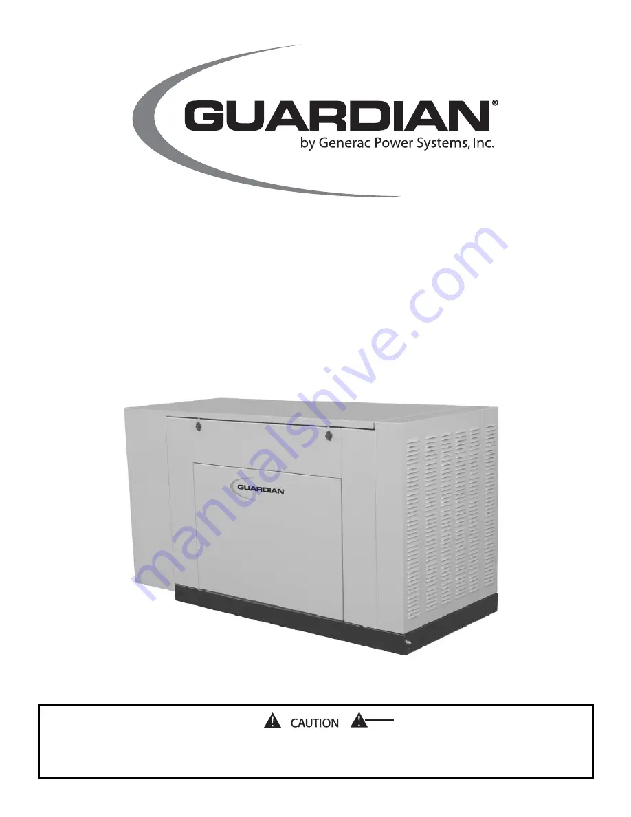
Owner’s Manual
ONLY QUALIFIED ELECTRICIANS OR CONTRACTORS
SHOULD ATTEMPT INSTALLATION!!
This manual should remain with the unit.
Liquid-cooled, Prepackaged
Standby Generators
Model Number: 004988-1
Страница 1: ...Owner s Manual ONLY QUALIFIED ELECTRICIANS OR CONTRACTORS SHOULD ATTEMPT INSTALLATION This manual should remain with the unit Liquid cooled Prepackaged Standby Generators Model Number 004988 1...
Страница 2: ...plosion hazard This symbol points out potential fire hazard This symbol points out potential electrical shock hazard The operator is responsible for proper and safe use of the equipment Generac strong...
Страница 3: ...solation Method 9 2 6 Total Circuit Isolation Method 10 2 7 Grounding the Generator 10 2 8 Generator AC Neutral Connections 10 2 9 Transfer Switch Start Signal Connections 10 2 10 Battery Installation...
Страница 4: ...ener ator is installed operated and serviced in accordance with the manufacturer s instructions and recommen dations Following installation do nothing that might render the unit unsafe or in noncompli...
Страница 5: ...is operating Failure to isolate the two electric system power sources from each other by such means will result in damage to the generator and may also result in injury or death to utility power work...
Страница 6: ...ture dust dirt lint construction grit and cor rosive vapors If a transfer switch is not included one may be pur chased separately from a Generac Authorized Dealer 1 3 AUTOMATIC SYSTEM OPERATION When t...
Страница 7: ...WITCH This switch is normally closed N C but is held open by engine oil pressure during engine running Should operating oil pressure drop below about 8 10 psi 55 68 kPa the switch contacts close the e...
Страница 8: ...ing when the low battery condition occurs the engine will continue to run as long as possible Battery voltage is NOT monitored during the crank cycle 1 7 8 ALARM RESET If the engine control board shut...
Страница 9: ...or set up should be 11 inches to 14 inches of water column 0 4 to 0 5 psi at all load ranges 1 12 RECONFIGURING THE FUEL SYSTEM NOTE All models are configured for natural gas from the factory To recon...
Страница 10: ...er The critical essential loads may need to be grouped together and wired into a sepa rate emergency distribution panel This generator can be installed in conjunction with an engineered Generac GTS ty...
Страница 11: ...evailing winds Install the generator as close as possible to the transfer switch This reduces the length of wiring and conduit Install the generator as close as possible to the fuel supply to reduce t...
Страница 12: ...AL CONNECTIONS Generac uses an UNGROUNDED AC neutral Grounding is recommended only at the main service entrance If the neutral wire is grounded and one of the phase loads becomes grounded the excessiv...
Страница 13: ...s must be at 100 percent state of charge before they are installed on the generator When using maintenance free batteries it is not nec essary to check the specific gravity or electrolyte level Have t...
Страница 14: ...ive red LEDs will not flash in this mode The control board will NOT activate the transfer output The control board WILL monitor all engine condi tions and shut down on all the faults listed in this do...
Страница 15: ...el is below the transfer back threshold This secondary function is only available with dip switch two in the OFF position standard ATS appli cation 3 3 MANUAL TRANSFER AND START UP To transfer electri...
Страница 16: ...en days for approximately 12 minutes If utility should fail during this exercise period the engine control board will transfer the load to the generator output and continue to run until util ity retur...
Страница 17: ...t system parts from this product get extremely hot and remain hot after shutdown High grass weeds brush leaves etc must remain clear of the exhaust Such materials may ignite and burn from the heat of...
Страница 18: ...t fan belts every three months Replace any damaged deteriorated worn or otherwise defec tive belt Check fan belt tension Thumb pressure exerted midway between pulleys should deflect about 3 8 to 5 8 i...
Страница 19: ...10 for cooling system recommen dations 4 6 MISCELLANEOUS MAINTENANCE 4 6 1 CLEANING THE GENERATOR Keep the generator as clean and as dry as possible Dirt and moisture that accumulates on internal gen...
Страница 20: ...injury Any area that houses a storage battery must be properly ventilated Do not allow smoking open flame sparks or any spark producing tools or equipment near the battery Battery electrolyte fluid is...
Страница 21: ...FORE removing the battery cable to prevent an over current condi tion from burning out sensitive control panel components and circuits Following all maintenance reverse these steps to insure the unit...
Страница 22: ...mal protection level Correct as necessary 5 Check the natural gas delivery system on gas engine driven units Tighten connections as necessary 6 Check the air inlets and outlets for debris Clean as nec...
Страница 23: ...ons or components and abnormal operating conditions Correct as necessary 14 Start and exercise the unit at full rated load use a load bank if the site load is not enough for at least 2 hours looking f...
Страница 24: ...park plugs 3 Clean regap or replace plugs Engine starts then shuts down 1 Engine oil level is low 1 Check oil and add oil as needed 2 Engine is overheated 2 Check cooling system for leaks 3 Defective...
Страница 25: ...Generac Power Systems Inc 23 Section 6 Installation Diagram Guardian Liquid cooled 27 kW and 30 kW Generators Installation Diagram Drawing No 0E8695...
Страница 26: ...Y COIL TRANSFER RELAY COIL TRANSFER SWITCH 15E N2 N1 13A 23 183 178 14 13 13A 0 14 14A 16 15 IC 13 13 11 14 13A 239 15A 1b 1a 16 15 1 16 16 15 2a 2b 1 15 ALL WIRES ARE 18 AWG 300 VOLT UL LISTED UNLESS...
Страница 27: ...6 0 86 0 0 1 7 10 11 12 9 8 4 6 5 2 3 15A 225 224 15E 239 14 14A 0A 13 0 0 11 14 13 12 8 9 10 6 7 85 225 14A 66 C1 239 15E 0 RED 0 0 85 85 14 BLK FS 0A 0 0 16 16 13 GND2 0 0 0 4 16 10 0 0 SM 4 10 16 7...
Страница 28: ...E SWITCH AUTO OFF MANUAL SWITCH SET EXERCISER LEGEND CONT SW2 SW1 TR1 RL1 NB ICT F2 RELAY 1 LEGEND ALTERNATOR ROTOR ALTERNATOR STATOR AR AS FUSE BAT POWER 15A AGC TYPE F1 TRANSFER SWITCH 6 5 3 4 2 5 1...
Страница 29: ...T TEMP IGNITION MODULE ON DISTRIBUTOR STARTER MOTOR IGNITION COIL CONTACTOR STARTER MOTOR SC 239 15A 225 224 15E 14 13 14A 11 12 10 7 8 9 4 6 5 2 1 3 0A 0 0 0 23 66 PCB GOV 225 14A 85 66 4 6 5 1 2 3 J...
Страница 30: ...E 30 TO 44 35 34 3 36 33 44 42 22 20 32 38 18 31 20 TO STARTER STARTER BOLT TO BLOCK ENGINE 18 TO 11 1 12 10 14 REAR BEARING 13 15 37 14 CARRIER 3 4 16 2 28 Generac Power Systems Inc Section 8 Explode...
Страница 31: ...21 022129 1 WASHER LOCK M8 5 16 22 045771 1 NUT HEX M8 1 25 G8 YEL CHR 23 051756 1 SCREW HHC M10 1 5 X 20 G8 8 24 046526 1 WASHER LOCK M10 25 022131 1 WASHER FLAT 3 8 M10 ZINC 26 055934M 1 CLAMP VINYL...
Страница 32: ...LATION TYPICAL OF ROOF PANEL THAT TO A 4 53 4 35 SUPPORT RADIATOR 33 44 55 5 5 53 4 36 4 18 4 26 58 8 5 4 8 4 A A A A 29 12 13 16 17 52 54 B 20 11 10 15 14 19 2 59 28 4 1 17 16 42 40 9 18 23 57 57 5 5...
Страница 33: ...BRACKET STIFFENING BACK 27 0E8001 1 MUFFLER BOX 28 0E8060 1 ROOF W GAS SPRING MNT 3 0L FRD 29 0E8406 1 BRACE FRONT TOP 30 0D3037A 1 LATCH 1 4 TURN NONLOCKING 31 0C7781 2 PAWL DOOR HSB 32 0E7794 1 SUPP...
Страница 34: ...32 Generac Power Systems Inc Section 8 Exploded Views and Parts Guardian Liquid cooled 27 kW and 30 kW Generators Control Panel Drawing No 0E7118 G...
Страница 35: ...CUIT BREAKER 33 0E7539A 1 DECAL TB1 HSB CONTROL PANEL ITEM PART NO QTY DESCRIPTION 34 0D4698 REF BLOCK TERM 20A 6 X 3 X 1100V 35 0E7252 1 BRACKET CB 221 5 X 10² 36 0C1229 1 DECAL WARNING ELECTRICAL SH...
Страница 36: ...8 57 35 16 18 19 48 48 42 41 44 45 31 30 43 21 7 78 47 42 38 1 2 47 43 26 42 42 69 28 REAR UPPER BAFFLE 40 36 6 7 5 35 37 15 36 8 3 14 3 12 29 73 35 36 10 34 35 27 Section 8 Exploded Views and Parts G...
Страница 37: ...0 9 42 046526 17 WASHER LOCK M10 ITEM PART NO QTY DESCRIPTION 43 022131 11 WASHER FLAT 3 8 M10 ZINC 44 059982 4 SCREW SHC M12 1 75 X 45 G10 9 45 098780 2 SCREW HHC M12 1 75 X 65 G8 8 46 051769 3 WASHE...
Страница 38: ...8 9 3 21 27 PUMP TO WATER 4 12 17 6 15 7 1 15 20 3 22 24 24 TO 2 12 TO A 18 13 14 12 Section 8 Exploded Views and Parts Guardian Liquid cooled 27 kW and 30 kW Generators Radiator Drawing No 0E8528 B 3...
Страница 39: ...2 035685 4 CLAMP HOSE 28 1 32 2 25 13 0E8562 1 FAN GUARD HSB 14 058443 4 SCREW CRIMPTITE 1 4 20 X 5 8 15 0C2454 9 SCREW TH FRM M6 1 X 16 N WA Z JS 17 048031C 1 CLAMP HOSE BAND 1 4 18 029032 1 HOSE 9 3...
Страница 40: ...er Systems Inc B 31 10 16 4 2 17 5 9 1 7 6 30 32 29 11 29 15 8 3 6 13 ANER 29 19 26 27 18 21 2 39 Section 8 Exploded Views and Parts Guardian Liquid cooled 27 kW and 30 kW Generators Fuel System Drawi...
Страница 41: ...E6123 1 INTAKE ADAPTER 3 0L FORD BOSCH 19 0E6586 1 GASKET BOSCH 32 20 0E4395 1 ACTUATOR BOSCH 32 GOVERNOR 21 057753B 1 HOSE 1 5 ID X 2 LG 20R4 25 047487 4 SCREW SHC M6 1 0 X 18 G12 9 26 022097 8 WASHE...
Страница 42: ...Generac Power Systems Inc 4 15 7 17 8 7 1 18 31 30 LEADS 5 2 6 21 9 3 20 11 12 10 19 14 Section 8 Exploded Views and Parts Guardian Liquid cooled 27 kW and 30 kW Generators Alternator Drawing No 0E866...
Страница 43: ...0L HSB LG GEAR 6 0E6076 1 REVCOR FAN 10 75 X 2 W PRESS DIS 7 046526 8 WASHER LOCK M10 8 051755 4 SCREW HHC M10 1 5 X 16 G8 8 9 04576100BK 4 STUD M14 2 0 X 490 G5 ZINC 3 0L FORD 2 5L FORD 04576100BF 4...
Страница 44: ...ESCRIPTION 11 022129 10 WASHER LOCK M8 5 16 12 045771 2 NUT HEX M8 1 25 G8 YEL CHR 13 0C2454 4 SCREW TH FRM M6 1X16 N WA Z JS 17 044149 2 GASKET EXHAUST RING 18 0E0170A 2 EXHAUST BLANKET 3 0L FORD HSB...
Страница 45: ...X 1 4 20 STEEL 10 037561 1 NUT WING 1 4 20 NYLK ITEM PART NO QTY DESCRIPTION 11 049226 8 WASHER LOCK M5 12 091526 4 SCREW PPHM M5 0 8 X 12 ZNC 13 052619 4 SCREW HHC M5 0 8 X 20 G8 8 14 051713 4 WASHER...
Страница 46: ...44 Generac Power Systems Inc Section 9 Notes Guardian Liquid cooled 27 kW and 30 kW Generators...
Страница 47: ...Generac Power Systems Inc 45 Section 9 Notes Guardian Liquid cooled 27 kW and 30 kW Generators...
Страница 48: ...ng due to the improper installation location in a harsh or saltwater environment or scratched where integrity of paint applied is compromised Failures caused by any contaminated fuels oils coolants or...