background image

Generac

®

Power Systems, Inc.

11

Section 3 – Maintenance

QUIETPACT 50 and 70 Recreational Vehicle Generators

2.8.7 OPERATION IN HIGH GRASS

OR BRUSH

Never operate the generator while the vehicle
is parked over high grass, weeds, brush,
leaves or any other combustible substance.
Such materials can ignite and burn from the
heat of the exhaust system. The generator
exhaust system becomes extremely hot dur-
ing operation and remains hot for a long time
after it has shut down.

3.1

CHECKING THE ENGINE OIL
LEVEL

Never operate the engine with the oil level
below the “Add” mark on the dipstick. Doing
this could damage the engine.

For oil capacities and requirements, see “Engine Oil
Requirements,” Section 1.6.2 (Page 6). Check the
engine crankcase oil level at least every eight hours of
operation, or before you use it. To check the engine
oil level, proceed as follows (see Figure 3.1):

1. Be sure the generator is as level as possible.
2. Remove the dipstick and wipe it dry with a clean,

lint-free cloth.

3. Install and tighten the dipstick cap; then, remove

it again. The oil level should be at the dipstick
“Full” mark.

4. If necessary, remove the oil fill cap on the rocker

cover and slowly add oil until it reaches the dip-
stick “Full” mark. DO NOT FILL ABOVE THE
“FULL” MARK.

5. Install and tighten the oil fill cap and the dipstick

before operating the engine.

3.2

CHANGING THE ENGINE OIL
AND/OR OIL FILTER

• Change the engine oil after the first 25 hours of

operation (after the 25-hour break-in period, see
Section 2.8.5, Page 10). Thereafter, change the 
oil every 100 operating hours. Change the oil more
frequently if operating consistently under heavy
load or at high ambient temperatures. 

• Change the engine oil filter after the first 25 hours

of operation, and every 100 operating hours there-
after.

To change the oil and/or oil filter, proceed as 
follows:

1. Run the engine until it is thoroughly warmed up

(at least five minutes) then shut OFF the engine.

2. With the engine still warm from running, remove

the oil drain plug (Figure 3.1). Drain the oil into
a suitable container.

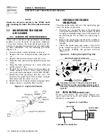
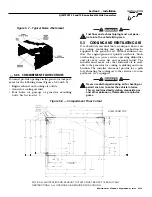
Figure 3.1 — Oil Dipstick/Fill Tube and

Location of Oil Drain Plug

3. After the oil has drained, replace the oil drain

plug. (If only changing the oil, go to step 7.)

4. With the oil drained, remove the old oil filter by

turning it counterclockwise (Figure 3.2).

5. Apply a light coating of clean engine oil to the gas-

ket of the new filter.

6. Screw the new filter on by hand until its gasket

lightly contacts the oil filter adapter. Then, tight-
en the filter an additional 3/4 to one turn.

7. Remove the dipstick and fill crankcase with the

proper type and amount of recommended oil (see
Section 1.6.2, Page 6). The engine crankcase can
hold about 1.8 liters. DO NOT FILL ABOVE THE
“FULL” MARK.

8. Install and tighten the dipstick before operating

the engine.

9. Start the engine and check for leaks.

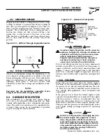
Figure 3.2 — Engine Oil Filter

Oil Dipstick

Oil Drain Hose

!

Содержание 004766-0

Страница 1: ... GUARDIAN 760cc OHVI V TWIN QUIETPACT INDUSTRIAL 55G Owner s Manual Air cooled Recreational Vehicle Generators QUIETPACT 50 and 70 50 Hz Frequency Models 004766 0 004767 0 This manual should remain with the unit ...

Страница 2: ... read this manual and thor oughly understand all instructions before using this equipment We also strongly recommend instructing other occupants in the vehicle to properly start and operate the generator This prepares them if they need to operate the equipment in an emergency CONTENTS This manual contains pertinent owner s information including warranty electrical diagrams exploded views and lists...

Страница 3: ...tor 14 3 12 Retorque the Head Bolts 14 3 13 Out of Service Procedure 14 3 13 1 Removal From Service 14 3 13 2 Return to Service 15 3 14 RV Generator Service Interval 15 Part II Installation Instructions 16 Safety Rules 17 Section 4 General Information 19 4 1 Purpose and Scope of the Installation Instructions 19 4 2 Safety 19 4 3 Standards Booklets 19 4 4 Equipment Description 19 4 5 Generator Engi...

Страница 4: ...ON ING ARE a inability to think coherently b nau sea c vomiting d twitching muscles e throb bing temples f dizziness g headaches h weakness and i sleepiness IF YOU EXPERI ENCE ANY OF THESE SYMPTOMS MOVE INTO FRESH AIR IMMEDIATELY IF SYMPTOMS PER SIST GET MEDICAL HELP Shut down the gener ator and do not operate it until it has been inspect ed and repaired Never sleep in the vehicle while the genset...

Страница 5: ...im is uncon scious apply first aid and get immediate medical help Never wear jewelry when working on this equip ment Jewelry can conduct electricity resulting in electric shock or may get caught in moving com ponents causing injury FIRE HAZARDS For fire safety the generator must be installed and maintained properly Installation always must comply with applicable codes standards laws and regulation...

Страница 6: ...OR 10W 30 5W 30 OR 5W 20 CHANGE EVERY 100 EVERY 250 HOURS REPLACE ELEMENT EVERY 100 HOURS CLEAN PREFILTER TEMPERATURE 40 F AND HIGHER WITH FILTER OIL CAPACITY OIL OIL FILTER AIR FILTER P A N E L 087769 072347 17 13 12 1 11 15 Behind Access Panel 10 5 2 3 4 14 8 16 19 1 1 GENERATOR IDENTIFICATION REFERENCE NUMBER IDENTIFICATION 1 Generator Air Intake Screen 2 Data Plate 3 Engine Start Stop Switch 4...

Страница 7: ...the rated watts of all electrical lighting appliance tool and motor loads the generator will power at one time This total should not be greater than the wattage capacity of the generator If an electrical device nameplate gives only volts and amps multiply volts times amps to obtain watts volts x amps watts Some electric motors require more watts of power or amps of cur rent for starting than for c...

Страница 8: ...ct more frequently for fuel leaks and other abnormalities 1 6 2 ENGINE OIL REQUIREMENTS Use only high quality detergent oil classified For Service SF and with an oil viscosity rating of SAE 10W 30 oil Do not pour in any additives to the rec ommended oil Engine crankcase capacity is 1 8 liters See Section 3 2 on page 11 for oil level check and filing procedures 1 6 3 GENERATOR SPECIFICATIONS Rotor ...

Страница 9: ...ing the engine cannot be cranked If you must replace the fuse use only an identical 7 5 amp replacement fuse 2 1 4 LINE BREAKERS Protects generator s AC output circiut against overload i e prevents unit from exceeding wattage amperage capacity The circuit breaker rat ings are as follows Figure 2 1 Typical Control Panel 2 2 OPTIONAL REMOTE START STOP PANEL A remote mounted Start Stop Panel Figure 2...

Страница 10: ...ay damage the generator 2 4 5 ENGINE EXHAUST GAS Before starting the generator engine you should be sure there is no way for exhaust gases to enter the vehicle interior and endanger people or animals Close windows doors and other openings in the vehi cle that if open might permit exhaust gases to enter the vehicle The generator engine releases DEADLY carbon monoxide gas through its exhaust system ...

Страница 11: ...lectrical loads are applied at reduced operating speeds such loads imposed on the engine when suf ficient power is not available may shorten engine life Never turn ON electrical loads until after the genera tor engine has started and stabilized at no load 2 7 2 DO NOT OVERLOAD THE GENERATOR You can read the rated wattage amperage capacity of your generator on the generator data decal see Section 1...

Страница 12: ...n circuit This circuit prevents trou blesome surges in the generator AC output voltage Voltage surge is a common cause of damage to elec tronic equipment 2 8 5 25 HOUR BREAK IN PERIOD The first 25 hours of operation is the break in period for the generator Properly breaking in the generator is essential to minimize fuel consumption and pro vide maximum engine performance During this 25 hour break ...

Страница 13: ...HANGING THE ENGINE OIL AND OR OIL FILTER Change the engine oil after the first 25 hours of operation after the 25 hour break in period see Section 2 8 5 Page 10 Thereafter change the oil every 100 operating hours Change the oil more frequently if operating consistently under heavy load or at high ambient temperatures Change the engine oil filter after the first 25 hours of operation and every 100 ...

Страница 14: ...lter Tabs at edges of paper filter must lock into slots on cover 8 Install the cover foam precleaner and paper filter 9 Replace knob to retain the filter in place Figure 3 3 Engine Air Cleaner 3 4 CHECKING THE ENGINE SPARK PLUG Clean the spark plug and reset the spark plug gap every 100 hours of operation 1 Clean the area around the base of the spark plug to keep dirt and debris out of the engine ...

Страница 15: ... the generator Water will enter the generator interior and cause problems and may also cont aminate the generator fuel system 3 8 BATTERY MAINTENANCE All lead acid batteries will discharge when not in use The generator battery should be inspected as follows 3 8 1 WEEKLY Inspect the battery posts and cables for tightness and corrosion Tighten and clean as necessary Check the battery fluid level of ...

Страница 16: ...e engine drives the generator rotor by means of a pulley and drive belt arrangement Drive belt tension was properly adjusted before the unit was shipped from the factory If you suspect that drive belt tension is incorrect contact a Generac Authorized Service Dealer 3 11 EXERCISING THE GENERATOR Generac recommends that you start and operate the generator at least once every seven days Let the unit ...

Страница 17: ...evel with distilled water DO NOT USE TAP WATER IN THE BAT TERY Recharge the battery to 100 percent state of charge or if defective replace the battery 3 Clean and wipe the entire generator 4 Reconnect the battery Observe battery polarity Damage may occur if the battery is connected incorrectly 5 Turn OFF all electrical loads Add fuel if neces sary and then start the engine 6 Allow the unit to warm...

Страница 18: ...PART II INSTALLATION INSTRUCTIONS ONLY QUALIFIED ELECTRICIANS OR CONTRACTORS SHOULD ATTEMPT INSTALLATION DANGER ...

Страница 19: ...ion initial start up and mainte nance of this equipment is carried out by a Generac Authorized Service Dealer The generator engine releases DEADLY carbon monoxide gas through its exhaust system This dangerous gas if breathed in sufficient concentra tions can cause unconsciousness or even death Never operate the generator set with the vehicle inside any garage or other enclosed area DO NOT OPERATE ...

Страница 20: ...nducting implement such as a rope or board to free the victim from the live conductor If the victim is unconscious apply first aid and get immediate medical help Never wear jewelry when working on this equip ment Jewelry can conduct electricity resulting in electric shock or may get caught in moving com ponents causing injury FIRE HAZARDS For fire safety the generator must be installed and maintai...

Страница 21: ...ufacturer s recommendations The following standards booklets latest revision are available from the sources indicated 1 NFPA Standard 501C Standard for Recreational Vehicles available from the National Fire Protection Association Batterymarch Park Quincy MA 02269 2 NFPA 70 NFPA Handbook of the National Electric Code available same as Item 1 3 ANSI C1 1975 and ANSI 119 2 1975 available from the Ame...

Страница 22: ...two horizontal beams These beams should consist of a 1 1 2 inch square 11 gauge steel tubing OR b 1 1 2 inch 11 gauge angle iron A typical sup porting frame with horizontal support tubing is shown in Figure 5 1 The generator can be installed so that it sits on top of the horizontal support tubing if the vehicle design permits Another method is to suspend the generator below the horizontal support ...

Страница 23: ...Figure 5 4 Clearances 5 2 2 COMPARTMENT CONSTRUCTION The generator compartment should be either con structed of or lined with 26 gauge galvanized steel NOTE Aluminum is NOT an acceptable alternative to galvanized steel due to aluminum s low melting point If the compartment is lined with galvanized steel it may be constructed of any material Generac rec ommends that the compartment be constructed o...

Страница 24: ...ard the compartment interior Do not install sound insulation or any absorbent material on the compartment floor interior Such materials will become soaked with combustible or explosive vapors and liq uids and will become a fire hazard Using a combination of sound insulating materials can often reduce noise more effectively than a single material For example a sheet of lead or visco elastic materia...

Страница 25: ...rheats Such overheating can cause serious operating difficulties and also may cause fire and personal injury The installer must make sure that sufficient air is avail able to the generator for cooling ventilating and com bustion The installer also must provide for a path for exhausting the cooling air to the exterior of a com partment if so equipped Never use discharged cooling air for heating or ...

Страница 26: ... INTAKE HOT AIR EXHAUST 3 8 16 WELDNUTS 8 PLACES FUEL FILTER REMOTE PANEL CONNECTOR AC OUTPUT HARNESS BATTERY CONNECTIONS FRONT TAILPIPE LOCATION FUEL INLET FUEL INLET 25 4 VIEW FROM TOP FRONT DOOR ACCESS FOR ALL REQUIRED MAINTENANCE NOTE ALL AIR INTAKES AND EXHAUST OUTLETS MUST BE KEPT CLEAR OF ANY OBSTRUCTIONS ALL OPEN AREA IS REQUIRED FOR COOLING POWERED BY GUARDIAN 760cc OHVI V TWIN QUIETPACT ...

Страница 27: ...ly with all codes standards and regulations pertaining to gasoline fuel systems used in recreational vehicle generators Properly install and maintain the fuel system and keep it entirely free of leaks Gasoline vapors must not enter the vehicle interior Factory installed generator fuel system components include a fuel filter b 12 volt DC electric pump c engine carburetor and d interconnecting lines...

Страница 28: ... air and tends to settle in low areas Even the slightest spark can ignite it and cause and explosion Only competent qualified people should be allowed to install test adjust or ser vice an LP gas fuel system Install the optional fuel system in compliance with applicable codes standards and regulations After the installation do not do anything that might ren der the system in noncompliance with app...

Страница 29: ...east 67 cubic feet per hour The inlet side of any pri mary regulator that supplies the generator must connect directly to a gas pressure tank Do NOT tee the generator line into a gas circuit feeding other areas 5 5 6 GASEOUS CARBURETION LP gas vapors should be supplied to the secondary regulator inlet at about 11 inches water column pos itive pressure The engine pistons draw air in during the inta...

Страница 30: ...garage or other enclosed area DO NOT OPERATE THE GENERATOR IF THE EXHAUST SYSTEM IS LEAKING OR HAS BEEN DAMAGED SYMPTOMS OF CARBON MONOX IDE POISONING ARE a inability to think coher ently b nausea c vomiting d twitching muscles e throbbing temples f dizziness g headaches h weakness and i sleepiness IF YOU EXPERIENCE ANY OF THESE SYMPTOMS MOVE INTO FRESH AIR IMMEDIATELY IF SYMP TOMS PERSIST GET MED...

Страница 31: ...plicable codes standards and regula tions 5 7 ELECTRICAL CONNECTIONS Be sure to read Section 5 6 on Page 28 The following general rules apply to electrical con nections in a recreational vehicle Qualified electricians who are familiar with applic able codes standards and regulations should install electrical wiring The wiring should comply with codes standards and regulations The National Electric...

Страница 32: ...g through wiring insulation Route conduit so it does not interfere with genera tor movement If you use metallic conduit vapor seal the end of the conduit where it enters the junction box Do this because flexible metallic conduit is not vapor proof along its entire length 5 7 5 ISOLATING DIFFERENT POWER SOURCES Connections from the junction box must terminate in a double pole double throw transfer ...

Страница 33: ...50 and 70 Recreational Vehicle Generators Figure 5 17 Installation With Isolation Receptacle POWERED BY GUARDIAN 760cc OHVI V TWIN QUIETPACT INDUSTRIAL 55G Figure 5 16 Transfer Switch Isolation Method POWERED BY GUARDIAN 760cc OHVI V TWIN QUIETPACT INDUSTRIAL 55G ...

Страница 34: ...m any source of heat sparks or flame Provide ventilation openings in the battery compart ment The minimum size of openings should be 2 square inches at the top of the compartment Mount the battery on a strong rigid supporting structure where leaks and spills of battery fluid will not cause damage 5 9 OPTIONAL ACCESSORIES A plug in receptacle Figure 5 19 is provided on the generator set above the m...

Страница 35: ...ay require more cranking for initial starting since the fuel lines have to be primed use of the primer switch will shorten this time 3 Let the engine warm up for about five minutes to allow internal temperatures to stabilize 4 Carefully inspect the engine generator for fuel oil and exhaust system leaks Before proceeding to the next step correct any leakage immediately 5 When all tests and adjustme...

Страница 36: ...justed EXHAUST SYSTEM Exhaust system complies with all applicable codes Exhaust system is properly and safely installed ELECTRICAL CONNECTIONS Connections comply with local code requirements and all National Electrical Codes Junction box is properly installed Wiring meets all standards All connections are correct Conduit is properly installed and sealed Generator is properly bonded to the vehicle ...

Страница 37: ... flooded 5 Wait 5 10 minutes try again 6 Fuel filter is clogged 6 Replace filter if clogged 7 Engine spark plugs defective 7 Clean regap or replace as needed 8 Bad ignition magneto on engine 8 Replace if defective 9 Bad carburetor 9 Adjust repair or replace 10 Dirty air cleaner 10 Clean or replace as needed Engine starts hard runs rough 1 Dirty engine air cleaner 1 Clean or replace as needed 2 Aut...

Страница 38: ...P HTO 0B SP1 SP2 0 0 SM FP CH BLK 34 12 0 0 13 SCR 16 SC 14 FS 0 15 14A 15 15 14A 2 4 3 2 4 3 17 0 WHITE BROWN BLUE L1 HM FUEL PRIME GT 230V SP1 SPARK PLUG 1 CYL TC TERMINAL CONN 4 TAB CONNECTOR GT TERMINAL GROUND 4 TAB LEGEND BCR BATTERY CHARGE RECTIFIER CB1 CIRCUIT BREAKER 25A QP50 CS CHOKE SOLENOID FP FUEL PUMP OR LPG SHUT OFF VALVE LOP SWITCH LOW OIL PRESSURE SC STARTER CONTACTOR SW1 SWITCH ST...

Страница 39: ... 18 18A HTO 85 RED FP CH CS 14 0 15 15 F1 13 14A 14 14 0B 14 TC SW2 SW1 18 14 17 0 GT 18 CB1 0I 44 BLACK RED T3 T1 11P P 14 GT 18 17 0I REMOTE PANEL CONNECTOR 4 90 2 0 2A 66 15 13 14 15 17 17 2A 0 15 77 0 K 66 4 2 17 0 2A 11S SUPPLIED BY CUSTOMER ELECTRONIC VOLTAGE REGULATOR 4 6 2A 0N 22P 44 11P 33 55 33 RED 4 55 R1 FIELD STATOR CLOSEST TO BEARING 44 11S 77 2 66 6 34 12 11 SC SM 16 13 BATTERY 12V ...

Страница 40: ...23 24 5 25 27 7 28 30 31 32 33 34 35 36 37 39 40 41 42 43 44 4 45 5 46 39 40 37 36 35 47 48 49 50 8 51 52 7 53 54 55 56 57 58 59 60 39 61 62 63 8 7 52 64 65 66 8 7 6 26 Section 9 Exploded Views and Parts Lists QUIETPACT 50 and 70 Recreational Vehicle Generators Control Panel Drawing No 0E1701 ...

Страница 41: ... 25 G8 8 33 0D9377 1 PANEL TOP CONTROL ITEM PART NO QTY DESCRIPTION 34 054502 1 CIRCUIT BREAKER 3 X 1 35 031879 4 WASHER FLAT 4 ZINC 36 043182 4 WASHER LOCK M3 37 051714 4 NUT HEX M3 0 5 G8 YEL CHR 38 092234 1 ASSY POTTED RV CNTL 39 049226 5 WASHER LOCK M5 40 051716 3 NUT HEX M5 0 8 G8 YEL CHR 41 023484R 2 BUSHING SNAP 42 0D3700 1 NUT FLANGE M6 1 0 NYLOK 43 0D9378 1 PANEL BOTTOM CONTROL 44 052619 ...

Страница 42: ...20 18 19 2 3 4 4 23 22 21 25 26 27 28 45 30 10 31 32 33 34 35 36 6 37 3 39 40 41 42 43 44 46 52 47 48 49 50 5126 52 57 56 55 53 54 50 53 58 8 59 60 61 A A TO CARB B B Section 9 Exploded Views and Parts Lists QUIETPACT 50 and 70 Recreational Vehicle Generators Base Pulley Drawing No 0E1775 ...

Страница 43: ... 1 PULLEY ALTERNATOR 2255 RPM 5 0 KW 50 Hz ONLY 0C1753D 1 PULLEY ALTERNATOR 2510 RPM 7 0 KW 50 Hz ONLY 30 075224F 1 PULLEY ENGINE 2700 RPM 5 0 KW 50 Hz ONLY 075224G 1 PULLEY ENGINE 2900 RPM 7 0 KW 50 Hz ONLY ITEM PART NO QTY DESCRIPTION 31 0E0586 1 GASKET BOTTOM AIR OUT QPRV 32 0D7176 4 WASHER SELF LOCKING 1 DIA 12GA 33 0E1334 1 SCREEN BOTTOM AIR OUT 34 0D8824 1 TRAY V TWIN RV 35 081105 2 NUT FLG ...

Страница 44: ... 42 4 5 6 7 5 8 10 5 11 40 6 14 15 16 12 2 2 13 19 9 5 17 6 5 18 2 20 21 22 9 23 24 25 26 27 28 29 30 31 32 33 3 34 35 36 30 31 30 37 38 41 3 44 43 5 47 38 48 46 5 40 48 Section 9 Exploded Views and Parts Lists QUIETPACT 50 and 70 Recreational Vehicle Generators Enclosure Drawing No 0E1011 B ...

Страница 45: ...NLY 24 0D9099 1 CUST CONN 4KW RV REMOTE 25 074908 4 SCREW HHTT M5 0 8 X 10 BP 26 022473 1 WASHER FLAT 1 4 M6 ZINC 27 022097 1 WASHER LOCK M6 1 4 28 022507 1 SCREW HHC 1 4 20 X 1 2 G5 29 0742600149 1 WIRE ASM BATT NEG QP RV 30 0C7968 4 NUT HEX JAM 3 8 16 BRASS 31 022237 2 WASHER LOCK 3 8 32 0C7423 1 STUD 3 8 16 X 2 1 4 BRASS 33 0742600151 1 GND WIRE C PNL TO STUD V T RV 34 0A4456 1 WASHER LOCK SPEC...

Страница 46: ...0 56 57 52 53 54 55 58 5 60 62 63 64 65 66 67 69 70 7 73 74 75 77 78 8 79 7 80 81 82 83 84 85 87 91 1 92 2 2 94 4 5 96 97 98 99 100 0 101 66 102 104 66 103 105 106 107 106 TO LP REGULATOR 108 114 115 116 113 112 111 110 109 A A A B C C B D Section 9 Exploded Views and Parts Lists QUIETPACT 50 and 70 Recreational Vehicle Generators Sheet Metal Drawing No 0E1012 B ...

Страница 47: ... CHOKE BRACKET GASOLINE ONLY 0D9400 1 BRACKET CHOKE LP ONLY ITEM PART NO QTY DESCRIPTION 57 0A7095 2 RHMS 4 40 X 5 16SEMS 58 0D9404 1 SPRING CHOKE RETURN 59 0D9801A 1 WRAP VALLEY UPPER SPCC 60 0C3018A 1 WRAPPER UPR 1 W M8 WELD NUT 61 0D9680A 1 WRAP VALLEY GTV760 RV SPCC 62 0D1143A 1 WRAPPER UPR 2 W M8 WELD NUT 63 0C3053 1 ASSY GROUND WIRE GV990 64 085011 1 INSULATOR ASM IGN 65 0D9852 2 ASSY IGNITI...

Страница 48: ...ETPACT 50 and 70 Recreational Vehicle Generators 760 V Twin Engine Drawing No 0E1014 B 54 53 42 48 45 46 47 43 56 58 50 49 59 61 60 20 23 51 40 41 39 30 31 29 3 38 37 21 35 36 33 34 33 28 27 9 16 44 2 7 17 18 19 22 1 2 15A 15B 15A 14 24 13 6 4 5 3 26 25 12 7 11 8 62 63 64 32 ...

Страница 49: ...1 2D OIL RELIEF 32 050873A 1 1 4 NPT PIPE PLUG 33 0C2991 2 E RING GOVERNOR ARM ITEM PART NO QTY DESCRIPTION 34 0D1667A 1 ARM GOVERNOR 35 0C2988 1 THRUST WASHER GOVERNOR 36 0C2992 1 BUSHING GOVERNOR LOWER 37 0C5732 1 ASSEMBLY SUMP WITH SLEEVE 38 0C2993 1 SEAL GOVERNOR SHAFT 39 0C3007 1 SEAL 42 I D CRANKSHAFT 40 0D9756 1 CONNECTOR 3 8NPT TO INVTD FLR 3 8OD 41 0C3006 10 SCREW HHFC M10 1 5 X 55mm 42 0...

Страница 50: ... your engine or a part component thereof has failed due to abuse neglect improper maintenance or unap proved modifications or the use of counterfeit and or grey market parts not made supplied or approved by Generac You are responsible for presenting your engine to a Generac Authorized Warranty Service Facility as soon as a prob lem occurs The warranty repairs should be completed in a reasonable am...

Страница 51: ...low Any such emissions related part repaired or replaced under the ECS Warranty shall be warranted for the remainder of the ECS Warranty Period prior to the first scheduled replacement point for such emissions related part 4 Repair or replacement of any warranted emissions related part under this ECS Warranty shall be performed at no charge to the owner at a Generac Authorized Warranty Service Fac...

Страница 52: ...ee year limited warranty Proof of purchase is required and must be presented to a Generac Authorized Warranty Service Facility prior to the performance of any warranty service All warranty expense allowances are subject to the conditions defined in Generac s SUPER SER RV VICE INFORMATION MANUAL THIS WARRANTY SHALL NOT APPLY TO THE FOLLOWING Generac Guardian generators that utilize non Generac repl...

Отзывы: