Generac Power Systems 004635-3 Скачать руководство пользователя страница 4

2

Section 1 — General Information

ATS “HS” Type Transfer Switch

1.1 INTRODUCTION

This manual has been prepared especially for the
purpose of familiarizing personnel with the design,
application, installation, operation and servicing of
the applicable equipment. Read the manual carefully
and comply with all instructions. This will help to
prevent accidents or damage to equipment that might
otherwise be caused by carelessness, incorrect appli-
cation, or improper procedures.

Every effort has been expended to make sure that the
contents of this manual are both accurate and cur-
rent. The manufacturer, however, reserves the right
to change, alter or otherwise improve the product at
any time without prior notice.

1.2 EQUIPMENT 

DESCRIPTION

The automatic transfer switch is used for transfer-
ring electrical load from a UTILITY (NORMAL) power
source to a EMERGENCY ( STANDBY) power source.
Such a transfer of electrical loads occurs automati-
cally when the UTILITY power source has failed or is
substantially reduced and the EMERGENCY source
voltage and frequency have reached an acceptable
level. The transfer switch prevents electrical feedback
between two different power sources (such as the
UTILITY and EMERGENCY sources) and, for that
reason, codes require it in all standby electric system
installations.

The transfer switch consists of a transfer mecha-
nism, a relay control, and a terminal strip for con-
nection of sensing wires.

This switch is suitable for control of motors, electric
discharge lamps, tungsten filament and electric heat-
ing equipment and the tungsten load does the switch
rating.

The transfer switch is for use in optional standby sys-
tems only.

The transfer switch is suitable for use on a circuit
capable of 10,000 rms symmetrical amperes, 240
VAC when protected by a circuit breaker without an
adjustable short time response or by fuses.

1.3 TRANSFER 

SWITCH 

DATA 

DECAL

A DATA DECAL is permanently affixed to the transfer
switch enclosure. Use this transfer switch only with
the specific limits shown on the DATA DECAL and on
other decals and labels that may be affixed to the
switch. This will prevent damage to equipment and
property.

When requesting information or ordering parts for this
equipment, make sure to include all information from
the DATA DECAL.

Record the Model and Serial numbers in the space pro-
vided below for future reference.

1.4 TRANSFER 

SWITCH 

ENCLOSURE

The standard switch enclosure is a National
Electrical Manufacturer’s Association (NEMA) 3R
type. NEMA 3R type enclosures primarily provide a
degree of protection against falling rain and sleet and
is not damaged by the formation of ice on the 
enclosure.

1.5  SAFE USE OF TRANSFER SWITCH

Before installing, operating or servicing this equip-
ment, read the SAFETY RULES (inside front cover)
carefully. Comply strictly with all SAFETY RULES to
prevent accidents and/or damage to the equipment.
The manufacturer recommends that a copy of the
SAFETY RULES are posted near the transfer switch.
Also, be sure to read all instructions and information
found on tags, labels and decals affixed to the equip-
ment.

Two publications that outline the safe use of transfer
switches are the following:

• NFPA 70; National Electrical Code
• UL 1008, STANDARD FOR SAFETY-AUTOMATIC

TRANSFER SWITCHES

MODEL #

SERIAL #

Содержание 004635-3

Страница 1: ...Automatic Transfer Switch Owner s Manual ATS HS Type Models 004635 3 200 Amp 250 Volts and 004678 2 100 Amp 250 Volts This manual should remain with the unit ...

Страница 2: ...e failure occurs must be isolated from the NORMAL UTILITY power source by means of an approved transfer switch Failure to properly isolate the NORMAL and STANDBY power sources from each other may result in injury or death to electric utility workers due to backfeed of electrical energy Improper or unauthorized installation operation service or repair of the equipment is extremely dangerous and may...

Страница 3: ... platform Work on this equipment only while standing on such insulative mats Never work on this equipment while physically or mentally fatigued Keep the transfer switch enclosure door closed and bolted at all times Only qualified personnel should be permitted access to the switch interior In case of an accident caused by electric shock immediately shut down the source of electrical power If this i...

Страница 4: ... equipment and the tungsten load does the switch rating The transfer switch is for use in optional standby sys tems only The transfer switch is suitable for use on a circuit capable of 10 000 rms symmetrical amperes 240 VAC when protected by a circuit breaker without an adjustable short time response or by fuses 1 3 TRANSFER SWITCH DATA DECAL A DATA DECAL is permanently affixed to the transfer swi...

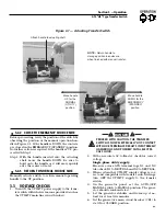
Страница 5: ...ll result in an extremely hazardous possibly lethal electri cal shock Wiring diagrams and electrical schematics are pro vided in this manual Power source and load connec tions are made at a transfer mechanism inside the switch enclosure 2 4 1 2 POLE MECHANISM These switches Figure 2 1 are used with a single phase system when the single phase NEUTRAL line is to be connected to a Neutral Lug and is ...

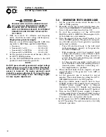
Страница 6: ...eeding with functional tests read and make sure all instructions and infor mation in this section are understood Also read the information and instructions of labels and decals affixed to the switch Note any options or accessories that might be installed and review their operation 3 2 MANUAL OPERATION Do NOT manually transfer under load Disconnect transfer switch from all power sources by approved...

Страница 7: ...Y HOT CONTACT WITH LIVE TERMINALS RESULTS IN EXTREMELY HAZARDOUS AND POSSIBLY FATAL ELECTRI CAL SHOCK 2 With an accurate AC voltmeter check for correct voltage Single phase utility supply Measure across ATS terminal lugs N1 and N2 Also check N1 to NEUTRAL and N2 to NEUTRAL 3 When certain that UTILITY supply voltage is cor rect and compatible with transfer switch ratings turn OFF the UTILITY supply...

Страница 8: ...switch to MANUAL When engine starts let it stabilize for a few minutes 4 Turn the generator s main circuit breaker to its ON or CLOSED position The generator now pow ers all LOAD circuits Check generator operation under load as follows Turn ON electrical loads to the full rated wattage amperage capacity of the generator DO NOT OVERLOAD With maximum rated load applied check voltage and frequency ac...

Страница 9: ...7 Section 4 Notes ATS HS Type Transfer Switch ...

Страница 10: ...8 Section 4 Notes ATS HS Type Transfer Switch ...

Страница 11: ...9 Section 4 Notes ATS HS Type Transfer Switch ...

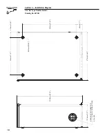
Страница 12: ...ation Diagram ATS HS Type Transfer Switch Drawing No 0E7081 377mm 14 84 508 5mm 20 02 KNOCKOUT SUITABLE FOR 1 1 1 2 AND 2 CONDUIT SIZE 3 PLACES 179 5mm 7 07 420mm 16 54 45mm 1 77 41 5mm 1 63 294mm 11 57 Ø6 3mm Ø0 25 10 ...

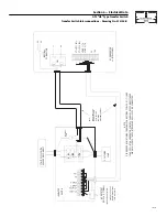
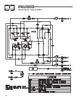
Страница 13: ... 1 N1 UTILITY 2 N2 LOAD 2 T2 23 194 CB1 NEUTRAL CONNECTION N1 N2 T1 T2 2 T E1 E2 2 E NEUTRAL LUG TRANSFER SWITCH UTILITY SUPPLY WITH SERVICE DISCONNECT LOAD CUSTOMER 194 23 LOAD 2 UTILITY 2 UTILITY 1 AC GENERATOR CONTROL PANEL NOTE POWER LEADS AND TRANSFER SWITCH LEADS MUST BE RUN IN TWO DIFFERENT CONDUITS LOAD 1 T1 22 LOAD 1 REMOTE TEST SWITCH OPTIONAL 11 44 33 Section 6 Electrical Data ATS HS Ty...

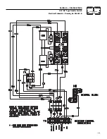
Страница 14: ...12 Section 6 Electrical Data ATS HS Type Transfer Switch Electrical Schematic Drawing No 0E6093 B ...

Страница 15: ...13 Section 6 Electrical Data ATS HS Type Transfer Switch Electrical Schematic Drawing No 0E6093 B ...
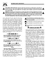
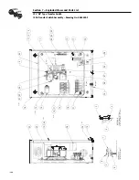
Страница 16: ...73591 T 30A 600V 30A 600V 073591 T 073591 T ENCLOSURE GROUND LUG ASSEMBLY POWER TERMINAL LUG ASSEMBLY NOTE TORQUE ITEM 3 TO 24 30 IN LBS DETAIL B B A A B B 0A9517 WAUKESHA WI OR ALUMINUM WIRE OF AT LEAST 75 C RATING RATING SWITCH GENERAC POWER SYSTEMS INC 120 240 CS3 8X16T CS3 8X16T 8X16T C2 VR2 STANDBY 0C2237fv Section 7 Exploded Views and Parts List ATS HS Type Transfer Switch 100A Transfer Swit...

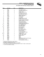
Страница 17: ...RIP 22 0E8443 1 DECAL SWITCH RATING 23 095282 1 DECAL LIVE CIRCUIT 24 067210A 1 DECAL GROUND LUG 25 0A9457 1 DECAL NEUTRAL 26 0A9517 1 DECAL MANUAL 5A FUSE 27 077036D 1 DECAL TEST SEQUENCE 3R 28 081221 1 DECAL UL LIST HSB 29 064101 4 NUT HEX FL WHIZ 3 8 16 30 0E6055 1 SUBPLT TRANSFER SWITCH HSB 31 063378 4 HOLDER CABLE TIE 32 028739 4 TIE WRAP UL 3 9 X 10 NATL 33 0E6193 1 BRACKET ARM EXTENDER 34 0...

Страница 18: ...24 A 12 17 38 34 36 3 A 5 25 2 1 4 057329 S ENCLOSURE GROUND LUG ASSEMBLY DETAIL A A 3 TO 72 1 IN LBS NOTE TORQUE ITEM CS C CS3 8X16T 8X16 CS3 8X16T C 8X16 22097 S WS3 4X1 4S 0A9517 SYSTEM VOLTAGE 120 240 SERIAL NUMBER 63378 T 63378 T 16 Section 7 Exploded Views and Parts List ATS HS Type Transfer Switch 200A Transfer Switch Assembly Drawing No 0E5782 J ...

Страница 19: ...HSB 19 0E6056 1 COVER TRANSFER SWITCH BOX HSB 20 0F0668 1 DECAL TRANSFER SWITCH 21 0A2595 1 DECAL TERMINAL STRIP 22 095282 1 DECAL LIVE CIRCUIT 23 0E8443 1 DECAL SWITCH RATING 24 064101 4 NUT LOCK FL 3 8 16 25 0E6055 1 SUBPLT TRANSFER SWITCH HSB 26 063378 5 HOLDER CABLE TIE 27 028739 5 TIE WRAP UL 3 9 X 10 NATL 28 0F2516 1 DECAL TRANSFER SWITCH DATA 200 29 067210A 1 DECAL GROUND LUG 30 0A9457 1 DE...

Страница 20: ...322 Select the prompt that describes the brand name of the generator THIS WARRANTY IS IN PLACE OF ALL OTHER WARRANTIES EXPRESSED OR IMPLIED SPECIFICALLY GENERAC MAKES NO OTHER WARRANTIES AS TO THE MERCHANTABILITY OR FITNESS FOR A PARTICULAR PURPOSE Some states do not allow limitations on how long an implied warranty lasts so the above limitation may not apply to you GENERAC S ONLY LIABILITY SHALL ...

Отзывы: