


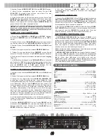


- Alternatively, the
BALANCED MASTER
(6) output jacks also con-
nects the mixer to the main amplifier using standard cables with
1/4"
TRS
connectors. We recommend using balanced cables if the distance
to your amp is
10
feet or more.
- The
BOOTH
(7) output jacks allow the connection of an additional
amplifier with
RCA
cables.
- The
ZONE
(5) output jacks allow the connection of an additional
amplifier with
RCA
cables.
- The
REC
(4) output jacks can be used to connect the mixer to the
record input of your recording unit, thus enabling you to record your mix.
4. Located on the rear panel are
2 PHONO
(
PH
)
/LINE
(
LN
) convertible
RCA
inputs (12, 16), &
5 LINE RCA INPUTS
(10, 9, 13, 17, 18). The
convertible
RCA
inputs for
CH 2
(16) &
CH 3
(12) allow
PH
and
LN
level
equipment to be connected to the mixer. To adjust the
CONVERTER
(s)
(11, 15), just flip the switch
UP
to operate
PH 1
or
PH 2
. Flip the switch
DOWN
to operate through
LN 2
or
LN 4
. The
PH INPUTS
only accept
turntables with a magnetic cartridge. When using (a) turntable(s), you
will need to ground the
RCA
cable(s) by screwing in the grounding
fork(s) to the
GROUNDING SCREW
(14) located in the back panel of
the
PDM
mixers. This is located in between the
CONVERTER SWITCH-
ES
(11, 15). The stereo
LN INPUTS
only accept line level inputs such as
a
CD
,
DAT
,
MiniDisc
,
etc
.
NOTE: WHEN USING TURNTABLES, NOT ATTACHING A GROUND MAY CAUSE A SYSTEM
"HUM."
5. Headphones may be plugged into the face-plate located
1/4" HEAD-
PHONE JACK
(26).
6. The
MIC 1
(49) input (located on the face panel) is a combination
XLR
&
1/4”
connector. The
MIC 2
(20) &
MIC 3
(19) inputs (in the rear panel)
accept only
1/4"
connectors. The mic inputs accept balanced & unbal-
anced connections.
7. The
BNC LAMP PORT
(22) (located on the face panel, above the
POWER SWITCH
(21)) is used to plug in a
12 V BNC
goose neck lamp
such as the
Gemini GNL-700
.
1. Once all of your connections have been made in the rear panel, turn
ON
the mixer by pressing the
POWER SWITCH
(21). Once turned
ON
,
the
POWER BAR LED
, containing the power symbol located in the
VU
METER
(23), will be illuminated. Turn
OFF
the mixer when not in use by
pressing the
POWER SWITCH
(21) to
OFF
. When the
PDM
mixer is
turned
OFF
the
POWER BAR LED
will not be illuminated.
2.
CHANNEL (CH) 1:
To bring this channel into program mix (
PGM
), you
must first decide which
LN
will be in use. Use the
LN SWITCH
(37) to
toggle from
LN 1
(18) to
MIC 3
(19) on this channel. Slowly raise the
CH
1 SLIDE CONTROL
(39) to a comfortable level, once you've selected
the proper line.
3.
CH 2:
To bring this channel into
PGM
, you must first decide which
LN
will be in use. Use the
LN SWITCH
(40) to toggle from
PH 1/LN 2
(16)
to
LN 3
(17) on this channel. Slowly raise the
CH 2 SLIDE CONTROL
(42) to a comfortable level, once you've selected the proper line.
4.
CH 3:
To bring this channel into
PGM
, you must first decide which
LN
will be in use. Use the
LN SWITCH
(43) to toggle from
PN 2/LN 4
(12)
to
LN 5
(13) on this channel. Slowly raise the
CH 3 SLIDE CONTROL
(45) to a comfortable level, once you've selected the proper line.
5.
CH 4:
To bring this channel into
PGM
, you must first decide which
LN
will be in use. Use the
LN SWITCH
(46) to toggle from
LN 6
(10) to
LN
7
(9) on this channel. Slowly raise the
CH 4 SLIDE CONTROL
(48) to a
comfortable level, once you've selected the proper line.
6.
CUE:
By connecting a set of headphones to the
HEADPHONE
(26)
jack, you can monitor any or all channels. Press the
CUE BUTTONS
(38, 41, 44, 47) for
CH
s
1
through
4
, respectively, to assign the
CH
(s) to
be monitored. The respective
CUE LED
indicators will glow when in use.
Use the rotary
CUE VOLUME CONTROL
(25) to adjust the
CUE
volume
without changing the overall mix. By moving the
CUE/PGM FADER
CONTROL
(24) to the
LEFT
you will be able to monitor the assigned
CUE
signal. Moving the
CUE/PGM FADER CONTROL
(24) to the
MID-
DLE
allows
CUE
mix with
PGM
. Moving the
CUE/PGM FADER CON-
TROL
(24) to the
RIGHT
allows you to monitor
PGM
output.
7.
ASSIGN:
There are
2
rotary controlled
X FADER ASSIGN SWITCH-
ES
(34, 35), each having
5
settings
OFF
,
1
,
2
,
3
, &
4
. The
LEFT
(34) not
Congratulations on purchasing a
Gemini PDM series 19"5U, 4 chan-
nel, rack mounted audio mixer
. This state of the art mixer is backed
by a
3
year warranty, excluding the
cross fader
. The
cross fader
is
backed by a separate
90
day warranty. Prior to use, we suggest that you
carefully read all the instructions.
- 5U, 19" rack mounted mixer
- 4 stereo channels
- 7 lines, 3 Mic, 2 phono/line convertible RCA inputs
- Master, record, booth, & zone RCA outputs
- 1/4" balanced master output
- 2 x 1/4" Mic inputs
- Dual 10 band graphic EQ with on/off switch & blue LED indicator
- Rotary zone, booth, & cue volume controls
- Stereo/mono switch
- Assignable cross fader
- Removable, user replaceable Rail Glide cross fader
- Push button cue section per channel with green LED indicator
- CUE/PGM fader control allowing cue mix
- XLR-1/4" combo Mic input
- 2 band rotary Mic EQ & volume controls
- Talk over feature
- BNC lamp port
- 1/4" headphone jack
NOTE: ABOVE FEATURES INCLUDED IN EACH MODEL IN THE PDM SERIES.
PDM-01 FACE:
- Master volume line fader control
PDM-02 FACE:
- 6 digital samples with volume, & speed rotary controls
- Rotary master volume control
- Master/Mic assignable echo effect switch with repeat & delay controls
PDM-03 FACE:
- 96 second digital sampler comprised of 5 memory banks with soft
touch backlit sample buttons
- Rotary assignable channel control for sample recording
- Sample parameter control with rotary level, pitch bend,
record/single/repeat controls
- Push button RoboPlay & cue sampler
- Rotary master volume control
1. All operating instructions should be read before using this equipment.
2. To reduce the risk of electrical shock, do not open the unit. Please
refer servicing to a qualified service technician.
3. Do not expose this unit to direct sunlight or to a heat source such as
a radiator or stove.
4. This unit should be cleaned only with a damp cloth. Avoid solvents or
other cleaning detergents.
5. When moving this equipment, it should be placed in its original carton
and packaging. This will reduce the risk of damage during transit.
6.
DO NOT EXPOSE THIS UNIT TO RAIN OR MOISTURE.
7.
DO NOT USE ANY SPRAY CLEANER OR LUBRICANT ON ANY
CONTROLS OR SWITCHES.
1. Before plugging the power cord in, make sure that the
VOLTAGE
SELECTOR
(1) switch is set to the correct voltage.
2. Located on the rear panel is the
115 V/230 V PLUG
(2). Before plug-
ging the power cord in, make sure the
POWER SWITCH
(21) located on
the face panel is turned
OFF
.
3. The
PDM
mixers have
5
sets of outputs:
- The
MASTER
(3) output jacks connects to the main amplifier with
RCA
cables.
(6)
INTRODUCTION:
FEATURES:
I
N THE
USA ~
IF YOU EXPERIENCE PROBLEMS WITH THIS UNIT CALL
G
EMINI
C
USTOMER
S
ERVICE AT
: 1 (732) 738-9003. D
O NOT ATTEMPT TO RETURN THIS EQUIPMENT
TO YOUR DEALER
.
OPERATING INSTRUCTIONS:
PRECAUTIONS:
CONNECTIONS:
Содержание PDM-01
Страница 3: ... 3 PDM 0 01 Front REAR ...
Страница 4: ... 4 4 PDM 0 02 Front REAR ...
Страница 5: ... 5 ...
Страница 19: ... 19 NOTES P PD DM M S SE ER RIIE ES S P PD DM M S SE ER RIIE ES S ...


