1010
771
En
Translation of the original operating instructions
Operating instructions and spare parts list
OptiStar CG08(-C)
Gun control unit
Страница 1: ...1010 771 En Translation of the original operating instructions Operating instructions and spare parts list OptiStar CG08 C Gun control unit ...
Страница 2: ...Gema Switzerland GmbH All other product names are trademarks or registered trademarks of their respective holders Reference is made in this manual to different trademarks or registered trademarks Such references do not mean that the manufacturers concerned approve of or are bound in any form by this manual We have endeavored to retain the preferred spelling of the trademarks and registered tradema...
Страница 3: ...r output guide values 9 Air flow rates 10 Design and function 11 General view 11 Operating elements 12 Input keys and switches 14 Connections 15 Pin assignment 16 CG08 C pin assignment 16 Scope of delivery 16 Typical properties Characteristics of the functions 17 Operating modes 17 Rinsing mode 18 Monitoring of wearing parts 19 Keyboard lock 20 Background illumination 20 Correction factor for the ...
Страница 4: ...ce life 39 Deactivation of wearing part monitoring 40 Setting the background illumination 40 Activate deactivate the keyboard lock 41 Checking the software version 41 RAM Reset 41 Shutdown 42 If in disuse for several days 42 CAN bus 43 Hardware 43 CAN bus cable plug assignment 44 System release in network operation 44 Determining user address Node ID and Baud rate 44 Fault remedying 47 Error diagn...
Страница 5: ...to electrically live or moving parts Possible consequences death or serious injury WARNING Improper use of the equipment could damage the machine or cause it to malfunction Possible consequences minor injuries or damage to equipment INFORMATION Useful tips and other information Proper use 1 The OptiStar CG08 C is built to the latest specification and conforms to the recognized technical safety reg...
Страница 6: ...acturer from any liability from resulting damage 6 The relevant accident prevention regulations as well as other generally recognized safety regulations occupational health and structural regulations are to be observed 7 Furthermore the country specific safety regulations also must be observed Product specific safety measures Installation work performed by the customer must be carried out accordin...
Страница 7: ... respective enclosed documents DANGER Working without operating instructions Working without operating instructions or with individual pages from the operating instructions may result in damage to property and personal injury if relevant safety information is not observed Before working with the device organize the required documents and read the section Safety regulations Work should only be carr...
Страница 8: ......
Страница 9: ...correct use and the risks associated with such actions are assumed by the user alone For a better understanding of the interrelationships in powder coating it is recommended that the operating instructions for all other components be read as well so as to be familiar with their functions too OptiStar CG08 C Gun control unit Reasonably foreseeable misuse Operation without the proper training Use wi...
Страница 10: ...tiGun GA03 yes WARNING The OptiStar CG08 C gun control unit may only be used with the specified gun types Electrical data OptiStar CG08 C Nominal input voltage 100 240 VAC Frequency 50 60 Hz Connected load 40 VA Nominal output voltage to the gun 12 V Nominal output current to the gun 1 2 A Protection type IP54 Temperature range 0 C 40 C 32 F 104 F Max surface temperature 85 C 185 F Approvals 0102 ...
Страница 11: ...pth 250 mm Height 177 mm Weight approx 3 7 kg Powder output guide values General conditions for the OptiFlow Injector Powder type Epoxy polyester Powder hose length m 12 Powder hose Ø mm 11 Power hose type POE with guide strips Input pressure bar 5 5 Correction value C0 Powder output zeroing adjustment Guide values for OptiStar CG08 with OptiFlow Injector IG06 All values in these tables are guide ...
Страница 12: ...nveying air flow rate 0 5 4 Nm h Supplementary air flow rate 0 4 5 Nm h Electrode rinsing air flow rate 0 3 0 Nm h NOTE The total air consumption for the device is determined based on the 3 configured air values These values apply for an internal control pressure of 5 5 bar NOTE The max total air consumption during the coating operation is 5 5 Nm h Total air 5 Nm h Conveying air Supplementary air ...
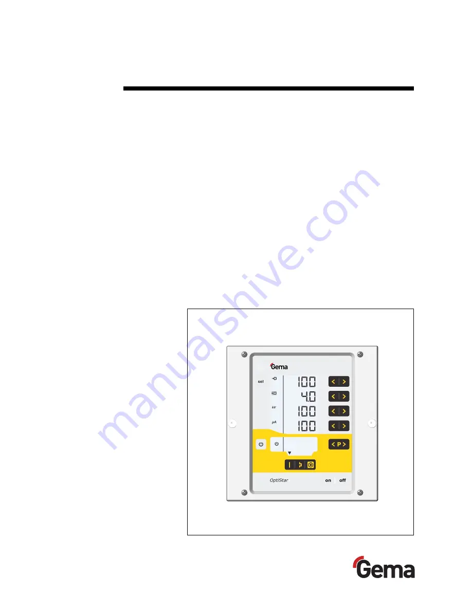
Страница 13: ...V 02 18 OptiStar CG08 C Product description 11 Design and function General view 1 Front plate with control and display elements 3 Back panel with interfaces 2 Enclosure 2 3 1 ...
Страница 14: ...sired values and system parameters Flashes when the possible range is exceeded A5 Display of program numbers error diagnosis codes and status information S1 Powder output display in S4 Total air volume display in Nm h S7 High voltage display in kV S9 Spraying current display in µA S12 remote Remote operation mode no local operation possible Remote operation mode is used as keyboard lock reduced op...
Страница 15: ...V 02 18 OptiStar CG08 C Product description 13 Displays and LEDs Level 2 Designation Function S3 Electrode rinsing air display in Nm h S19 Display illumination 0 8 S3 S19 ...
Страница 16: ...tch between display levels T10 T11 Program change T12 Gun release Switchover to system parameter mode Press for at least 5 secs T13 Preset mode for flat parts fixed values T14 Preset mode for complex parts with depressions fixed values T15 Preset mode for overcoating parts already coated fixed values T16 T17 Power switch On Off T12 T1 T2 T3 T4 T5 T6 T7 T8 T10 T11 T16 T17 T9 T13 T14 T15 ...
Страница 17: ...air hoses cables Connection Description 1 1 Main air IN Compressed air connection 2 1 Power IN Mains cable connection 2 2 Gun Gun cable connection 2 3 Aux CAN bus connection IN 2 4 Aux CAN bus connection OUT 1 4 Electrode rinsing air connection 1 3 Supplementary air connection 1 2 Conveying air connection Grounding connection ...
Страница 18: ...2 Remote control 1 GM03 3 Ground 4 Trigger 5 Remote control 2 GM03 6 Oscillator 7 Grounding PE CG08 C pin assignment CAN IN plug with 4 pins 2 3 Aux 1 Ground 2 24 VDC 3 CAN high 4 CAN low Enclosure shield CAN OUT socket with 4 pins 2 4 Aux 1 Ground 2 24 VDC 3 CAN high 4 CAN low Enclosure shield Scope of delivery Mains cable Quick start instructions and operating manual PE 3 1 2 3 1 2 4 5 PE 6 4 3 ...
Страница 19: ... profiles Application mode for recoating parts already coated This application mode is suitable for the overcoating of workpieces which are already coated In this operating modes current µA and high voltage kV are preset while powder and air volumes can be set and stored for each application mode Adjustable operating mode Program mode In this operating mode 250 individually definable programs P001...
Страница 20: ...ntrol The high voltage and spray current values and their symbols are depicted in red Rinsing mode The PowerClean mode is used to blow powder accumulations and moisture out of the powder hose injector and gun using compressed air NOTE The rinsing mode can only be activated from standby mode namely by pressing the corresponding keys on the gun control unit or also by an optional bus connection such...
Страница 21: ...t be explained Service life Operating time after which wearing parts should be replaced defined by the operator Minus days Number of hours past the selected service life that the wearing part has continued to be used Operating life Effective time during which the wearing part was in operation service life plus minus days if any Remaining service life displayed value where not in the minus range Th...
Страница 22: ...k The keyboard lock status remains stored when switching the equipment off and on The keyboard lock is cancelled if a RAM reset is performed On the OptiStar CG08 C gun control unit automatic device an external interlocking by remote input can also take place These two locking features are independent which means if the local interlocking is deactivated the external interlocking remains activated a...
Страница 23: ...rol unit enables a zeroing out of the powder output This allows for compensation to different powder hose lengths connecting to the pistol The correction factor C0 can be selected such that no powder is output when the powder share is reduced to 0 see also Initial start up Setting correction factor for powder output ...
Страница 24: ......
Страница 25: ...lowing general conditions impacting the coating results must be taken into consideration Gun control unit correctly connected Gun correctly connected Corresponding power and compressed air supply available Powder preparation and powder quality Mounting instructions The OptiStar CG08 C gun control unit is mounted into place using 2xM6 screws on the front side ...
Страница 26: ...ructions Connection instructions overview 1 2 NOTE Use clamp to connect grounding cable to the cabin or the suspension arrangement Check ground connections with Ohm meter and ensure 1 MOhm or less 3 4 5 6 Maintenance unit Injector Gun 5 5 bar 6 0 bar 6 5 bar ...
Страница 27: ...V 02 18 OptiStar CG08 C Commissioning 25 7 8 9 10 NOTE The compressed air must be free of oil and water ...
Страница 28: ......
Страница 29: ... and requested manually or by remote interface CAN Entering the system parameters 1 Turn on the gun control unit with the ON key 2 Hold key down for 5 seconds The display switches to the following level 3 The system parameter number is shown in the display A1 with a P placed in front 4 Set the corresponding system parameter value with the T5 or T6 key The value of the adjusted system parameter app...
Страница 30: ... pressure 0 P in 5 5 bar 1 P in 6 bar 2 P in 6 5 bar 5 5 6 0 6 5 P03 Unit of measurement air 0 Nm h 1 scfm P04 Interface type 0 Deactivated 1 Automatic recognition OFF Auto P05 CAN Baud rate 0 20 kBit s 1 50 kBit s 2 100 kBit s 3 125 kBit s 4 250 kBit s 5 500 kBit s 6 800 kBit s 7 1 MBit s 2 0 5 0 1 0 0 1 2 5 2 5 0 5 0 0 8 0 0 1 0 0 0 P06 CAN Node ID 1 127 P07 Reserve P08 Reserve P09 Reserve P10 L...
Страница 31: ...r P00 is set to 3 when device is starting NOTE A wrong parameterization leads to various malfunctions The system parameter P00 must be set to 3 Automatic device System parameter P03 This parameter is used to determine the measuring unit for all airs total air and electrode rinsing air If the parameter is set to 1 scfm then all air values are shown in this measuring unit These lines are displayed i...
Страница 32: ...the switching on procedure the log messages are also recorded onto the SD card The data are record in the MESSAGES LOG file in the root directory Once this file reaches a size of 32 MB it is renamed as MESSAGES 1 and a new MESSAGES LOG file is then created Parameter value Level of detail of reports 0 no messages 1 few details 5 all messages NOTE Real time timings can be impaired from a level of de...
Страница 33: ...et values for high voltage and spray current Application mode Preset µA Preset kV flat parts 100 100 complex parts 22 100 overcoated 10 100 3 The air values for total air powder output and electrode rinsing air can be individually defined and are saved in the programs Starting the user defined operating mode Program mode 1 Turn on the gun control unit with the ON key 2 Press program key 3 Select d...
Страница 34: ...g coating requests Setting the powder output 1 Adjust the powder output volume e g according to the desired coating thickness Factory default setting of 50 is recommended for initial operation The total air volume is thereby kept constant automatically by the control unit NOTE As a factory default value a powder rate of 50 and a total air volume of 4 Nm h are recommended By inserting values which ...
Страница 35: ...zles with air rinsed deflector plates the factory default value is approx 0 5 Nm h 3 If in this display level is no operation for 3 seconds the first display level is switched over independently Correction values The OptiStar OptiStar CG08 C Gun control unit can be adapted with the correction values optimally to local conditions e g the adjustment of different powder outputs in the plant Entering ...
Страница 36: ...en the P00 device type is changed 2 A correction value is set to its default value if it is outside of the value range after the P00 device type has been changed 7 Press key Display returns to the first level display Powder output powder hose correction NOTE The settings in the following example are carried out for each gun individually Powder output corrections are made at the first start up afte...
Страница 37: ...5 gr 8 If no powder is expelled from the gun return to the system parameter mode and increase the minimum powder output value C0 range 0 5 3 0 Nm h 9 If too much powder is expelled from the gun return to the system parameter mode and decrease the minimum powder output value C0 range 0 5 3 0 Nm h 10 Repeat steps 6 and 7 until the powder output amounts to 10 15 g Annotate the adjusted minimum powder...
Страница 38: ...0 250 gr C1 80 200 gr 3 C1 100 280 gr C1 71 200 gr etc Correction factor diagram Correction factor diagram NOTE The hose length correction factor is chosen in such a way that no powder is visible if the powder portion is 0 by increasing the value the powder becomes visible then This performance depends on the hose length and the hose diameter Daily correction value C2 NOTE The daily correction val...
Страница 39: ...ary release signals are present 1 2 Select the cleaning function Key Cleaning function Powder hose cleaning with increasing air volume Powder hose cleaning with constant air volume The symbol S15 or S16 of the selected function is displayed in blue 3 During the mode Powder hose cleaning with increasing air volume all airflows are increased step by step after starting the cleaning procedure and the...
Страница 40: ...l 2 Press and at same time Monitoring is activated During the first activation a value of 1 is shown as the start value If monitoring has already been activated at some earlier point then the last stored value is displayed 3 Set the desired service life for each wearing part using the or 4 The reverse counter is then activated and runs only during active coating 5 If the selected service life is e...
Страница 41: ...ample for wearing part no 3 Read minus days 7 5 days Selected service life 200 days Operating life 207 5 days Display of remaining service life range 0 1 500 days and Deactivation of monitoring or adjustment of service life Quit wearing parts monitoring Service life expired negative value display blinks Monitoring deactivated and Activation of montioring ...
Страница 42: ...iStar CG08 C Deactivation of wearing part monitoring 1 Press and key simultaneously Monitoring is deactivated Setting the background illumination 1 Press key The display switches to the following level 2 Select the desired brightness ...
Страница 43: ...d RAM Reset The RAM reset enables a restore of factory settings of the OptiStar CG08 gun control unit All parameters except P00 and correction values as well as all user defined values in the Program mode and Preset mode will be overwritten with factory default An active keyboard lock will be deactivated NOTE By resetting the RAM all user made settings will be set to factory default 1 Switch off t...
Страница 44: ...Release gun trigger 2 Switch off the control unit NOTE The adjustments for high voltage powder output volume and electrode rinsing air remain stored If in disuse for several days 1 Separate from power mains 2 Clean the coating equipment see the corresponding operating manual 3 Turn off the compressed air main supply ...
Страница 45: ...ed values process data All actual values process data All control values All system parameters except Baud rate and CAN address All error messages All special parameters such as software version daily correction powder output correction etc Hardware The OptiStar control units are connected to the central PLC control unit via 4 pin CAN bus cables The last bus client is fitted with a terminal plug w...
Страница 46: ...e logic starts and stops the powder conveying and high voltage The release is determined due to the several internal and external signals Signal Designation Ext Release System signal on mains plug Trigger Gun connected Gun release Local or command via Remote Interface Error Lock Device error System Lock Parameter input PLC control with CAN bus Terminal resistor OptiStar no 1 OptiStar no 2 OptiStar...
Страница 47: ... Node ID value can be set by editing the system parameter P06 Baud rate system parameter P05 P05 value Baud rate 0 20 kBit s 1 50 kBit s 2 100 kBit s 3 125 kBit s 4 250 kBit s 5 500 kBit s 6 800 kBit s 7 1 Mbit s Default value of system parameter P05 3 The Baud rate is selected with 125 kBits as default This setting permits a maximum cable length of approx 500 m from the first to the last CAN bus ...
Страница 48: ......
Страница 49: ...ally acknowledged with the keys T10 or T11 The errors are displayed in the order of their appearance The T10 and T11 keys cannot be used for other functions as long as an error code is still shown Here is a list of all possible help codes for the OptiStar CG08 C Gun control unit Code Description Criteria Remedy Pneumatics H06 Trigger valve Solenoid coil current lower than preset limiting value Val...
Страница 50: ...ervice EEPROM equipment memory H24 EEPROM content invalid EEPROM error contact Gema Service H25 Timeout during EEPROM writing EEPROM error contact Gema Service H26 Values not correctly stored in EEPROM during switching off EEPROM error contact Gema Service H27 EEPROM verification erroneous EEPROM error contact Gema Service CAN bus H40 Permanent CAN bus error The CAN controller changes into BUS OFF...
Страница 51: ... in limit switch motor throttle defective contact Gema Service H66 Electrode rinsing air throttle does not move Short circuit in limit switch motor throttle defective contact Gema Service H68 Conveying air position lost Lost steps limit switch defective throttle motor defective contact Gema Service H69 Supplementary air position lost Lost steps limit switch defective throttle motor defective conta...
Страница 52: ......
Страница 53: ...iece Clamp Ø 18 15 mm When ordering cable or hose material the required length must also be given The spare part numbers of this bulk stock is always marked with an Wearing parts are always marked with a All dimensions of plastic hoses are specified with the external and internal diameter Example Ø 8 6 mm 8 mm outside diameter o d 6 mm inside diameter i d WARNING Only original Gema spare parts sho...
Страница 54: ...e parts list OptiStar CG08 C OptiStar CG08 C Gun control unit 1 OptiStar CG08 Gun control unit complete 1009 299 OptiStar CG08 C Gun control unit complete 1009 300 2 Cover 1008 301 OptiStar CG08 C Gun control unit 1 2 ...
Страница 55: ... 2 Spacer sleeve Ø 3 1 6x15 mm 3 PCB Powerboard V2 0 1009 865 4 Spacer sleeve Ø 3 2 6x7 mm 5 Front frame complete incl pos 5 1 1007 048 5 1 Special screw 1007 019 6 Special screw M4x20 7 mm 1003 000 7 Front plate gasket 1007 042 9 Spacer sleeve Ø 3 6 7x5 mm 10 Display 1007 044 11 Washer Ø 3 2 7x0 5 mm 12 Locknut M3 13 Power pack 24 VDC 1009 849 OptiStar CG08 C Front plate and power pack 3 5 4 10 9...
Страница 56: ...mplett nur CG08 C 1009 068 3 Elbow plug in connection Ø 8 Ø 8 mm 230 995 4 Solenoid valve Ø 8 Ø 8 mm NW 3 4 24 VDC 1003 914 5 Motor throttle complete 1000 064 6 Plastic tube Ø 8 6 mm 103 152 7 Fluidizing pad 1 8 a 237 264 8 Cap screw M4x16 mm 216 801 Please indicate length OptiStar CG08 C inside rear wall 2 7 5 5 6 1 3 5 4 8 ...
Страница 57: ...kink protection M12x1 mm Ø 8 mm 201 316 3 1 Conveying air hose Ø 8 6 mm red 103 500 3 2 Quick release coupling for conveying air hose NW5 Ø 8 mm 261 645 4 Quick release connection NW 5 mm 1004 272 4 1 Hose Ø 8 6 mm 103 756 5 CAN bus cable 0 5 m CG08 C only 1002 655 CAN bus cable 4 5 m CG08 C only 387 592 CAN bus cable 5 5 m CG08 C only 388 521 CAN bus cable 6 0 m CG08 C only 388 530 6 Bus terminal...