ADV200-HC Manual
Page 47 of 55
Beam) to a known position and write it in
the “Known position” parameter
HOIST&CRANE \ H&C SERVICE \ Known position
26.02.13
11198
Only for
drives
with
Antisway
active
Specify analog input and write the full-
scale to be used to send and receive
rope length measurement (value must
be greater than maximum rope length).
The parameter must be the same on the
HOIST GANTRY and TROLLEY drives
linked for antisway.
HOIST&CRANE \ ANTISWAY \ Rope length src
26.09.03
HOIST&CRANE \ ANTISWAY \ Rope length scale
26.09.04
11108
11174
14
Activate and configure the selected
functions.
15
Configure thresholds and activities for
alarms
HOIST&CRANE \ ALARM CONFIG
26.16
16
Save and reset the drive.
4.2.5
Procedure for manual calibration of inertia
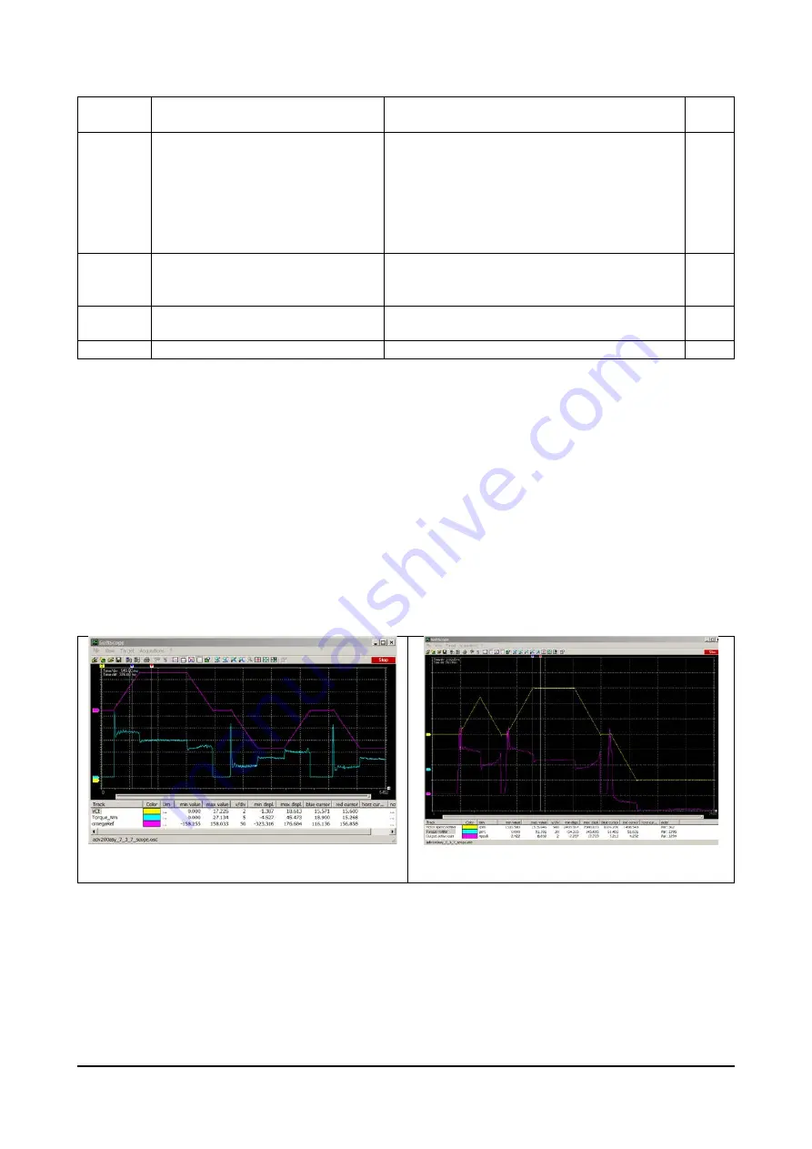
Acquire an up and down phase with SoftScope. The acquired variables are vTorque_Nm and
vSpeed_Rad_sec (see chapter “List of parameters monitorable with SoftScope SW oscilloscope for more
information). If system inertia is dominated by the constant, the hoisted load is not important (it can also be
zero).
The magenta line shows speed, the blue line shows torque. A rise (positive speed) and a descent are recorded.
The torque line clearly shows the gap between acceleration (blue cursor) and movement at constant speed
(red cursor). The difference between the two torques is the torque needed to accelerate (TorqueAcc). The
maximum speed reached in rad/s is shown in Vmax. Acceleration time (tAcc) is the time taken to reach it from
zero. The values are easily derived from the graph.
The moment of inertia in kg/m^2, is given by:
J = TorqueAcc * tAcc / Vmax
Figura 1: acquisizione Foc e Sls
Figura 2: acquisizione V/f
Note: in V/f, torque is not constant during acceleration. This is due to the less precise estimation method
used for V/f. In any case, torque delta value is used at the end of acceleration.
Содержание ADV200 ASY
Страница 1: ...ADV200 HC English Instruction manual ...


