0
None
1
Zero
2
Hold
3
Flash
4
Max. peak display
5
Min. peak display
6
Delta peak display
7
Peak memory reset
8
Zero + peak memory reset
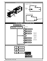
18
Potentiometer calibration
19 Offset
• Protection
0
None
1
Zero
2
Hold
3
Flash
4
Max. peak display
5
Min. peak display
6
Delta peak display
7
Peak memory reset
8
Zero + peak memory reset
17 Keylock (
d.I.
only)
18 Potentiometer calibration
(
t.U.
and
t.d.
only)
19 OFFSET (
t.U.
and
t.d.
only)
d.I. - t. u. - t. d.
• User Calibration
.......
• Custom Linearization
min…max scale
of input selected in t.P
Decimal point position for
main input scale
Minimum limit of main
input scale
Maximum limit of main
input scale
Offset correction of main
input
-999 to 999
scale points
min…max scale
of input selected in t.P
Select function of
digital input
(R77 only)
dP
Format
0
XXXX
1
XXX.X
2 *
XX.XX
3 *
X.XXX
(*) not available for TC,
RTD, PTC and NTC scales
Raise key function
(active only in
P.V.selection)
Custom Linearization of
main input
Step 0
(beginning of scale value)
Display limits
(-1999 to 9999)
Step 32
(full scale value)
Display limits
(-1999 to 9999)
Step 33
mV beginning
of scale
Step 34
mV full scale
Step 35
mV at 50°C
(*)
(*)
(*)
(*) only for CPU, TC_LIN and tP = TC CUSTOM
U.C. CPU T Function
2
Custom RTD sensor
3
Custom PTC sensor
4
Custom NTC sensor
5 Potentiometer (0 to 1V)
Digital filter on main input
Digital filter on process
variable display
0.0 to 20.0 sec
0.0 to 9.9
scale points
Calibration of
minimum
Calibration of
maximum
the n step value corresponds to input:
mV beginning scale + n *
Δ
mV
Δ
mV = (mV full scale - mV beginning scale) / 32
Protection code
Value
0 Display and setting
of all parameters
+4 to disable In pages
+16 to enable maintenance of reset latch at power-off (for linear inputs only)
+32 base configuration (the following parameters will not be displayed:
In: Ft, Fd, Of
+128 disabled of all the menu except PA
f.t
f.d
dP
L.s
x.s
o.f
d.I.
t.U.
Ln
0.0.
3.2.
3.3.
3.4.
3.5.
Pr
U.(.
(.L.
(.x.
Lower key function
(active only in
P.V.selection)
t.d.
5
81600G_MHW_4T48_07-2011_ENG
• Interface for GEFRAN instrument configuration
KIT PC USB / RS485 o TTL
• ORDERING CODE
Kit for PC via the USB port (Windows environment) for GEFRAN instruments configuration:
Lets you read or write all of the parameters
• A single software for all models
• Easy and rapid configuration
• Saving and management of parameter recipes
• On-line trend and saving of historical data
Component Kit:
- Connection cable PC USB ... port TTL
- Connection cable PC USB ... RS485 port
- Serial line converter
- CD SW GF Express installation
GF_eXK-2-0-0 cod F049095
5 / 7


