9
IR CHANNEL CONFIGURATION
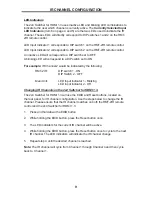
LED Indicators
The 2x4 Switcher for HDMI 1.3 uses inactive LED and blinking LED combinations to
indicate to the user which channel is currently active. The
Currently Selected Input
LED Indicators
(Item 6 on page 4 and 5) are the two LEDs used to indicate the IR
channel. These LED’s will directly correspond to DIP switches 1 and 2 on the RMT-
2IR remote control.
LED Input Indicator 1 corresponds to DIP switch 1 on the RMT-2IR remote control.
LED Input Indicator 2 corresponds to DIP switch 2 on the RMT-2IR remote control.
An inactive LED will correspond to a DIP switch set to OFF.
A blinking LED will correspond to a DIP switch set to ON.
For example:
IR Channel 2 would be indicated by the following:
RMT-2IR:
DIP switch 1 - ON
DIP Switch 2 - OFF
Main Unit:
LED Input Indicator 1 - Blinking
LED Input Indicator 2 - Off
Changing IR Channels on the 2x4 Switcher for HDMI 1.3.
The 2x4 Switcher for HDMI 1.3 will use the EDID and Reset buttons, located on
the rear panel, for IR channel confi guration. Use the steps below to change the IR
channel. Please ensure that the IR channel matches on both the RMT-2IR remote
control and the 2x4 Switcher for HDMI 1.3.
1.
Press and hold down the EDID button.
2.
While holding the EDID button, press the Reset button once.
3.
The LED indicators for the current IR channel will be active.
4.
While holding the EDID button, press the Reset button once to cycle to the next
IR channel. The LED indicators will indicate the IR channel change.
5.
Repeat step 4 until the desired channel is reached.
Note:
The IR channel will cycle from Channel 1 through Channel 4 and then cycle
back to Channel 1.


