background image


POWER CONNECTOR ASSIGNMENTS


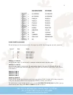
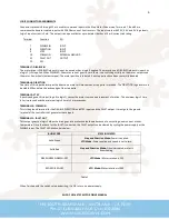
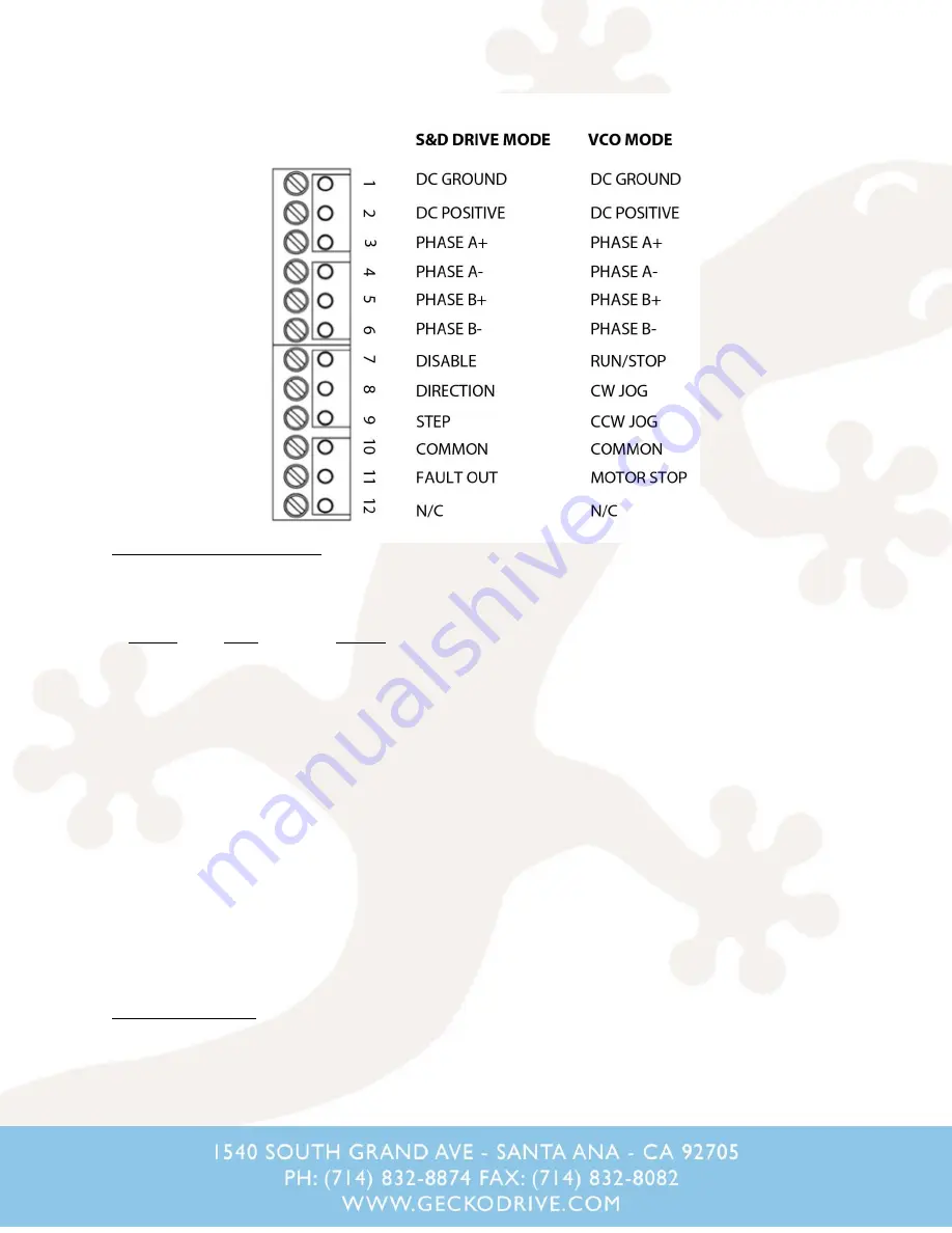
The terminal connection is broken into two blocks of six connections, with the first six being power and motor connections. 


     Terminal


Name


Function


1


GND


DC Power supply (-)


2


VDC+


DC Power supply (+)


3


 A


Motor winding A


4


/A


Motor winding A


5


 B


Motor winding B


6


/B


Motor winding B


TERMINAL 1: DC GROUND


Connect the power supply '-' to this terminal. This connection must be hard-wired to the power supply.


TERMINAL 2: DC POSITIVE


Connect the power supply '+' to this terminal. The power supply voltage must be between 18 VDC and 80 VDC and this 
connection must be hard-wired to the power supply. Do not use a switch, relay contact or any other device in series with this 
wired connection.


TERMINAL 3: PHASE A+


TERMINAL 4: PHASE A-


TERMINAL 5: PHASE B+


TERMINAL 6: PHASE B-


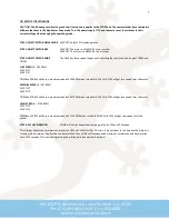
TRIMPOT ADJUSTMENTS


TRIM1 and TRIM2 are used to maximize motor smoothness at speeds below 50 RPM. The Digital Self-Test feature can useful in 
making these adjustments. While the motor is turning, adjust TRIM1 for minimum motor vibration.


The rest of this user's manual is divided into two sections. Use the 

G216 STEP MOTOR DRIVE MANUAL

 if the G216 is used as a 

conventional step motor drive. Use the 

G216 VCO MANUAL

 if the G216 VCO is used.


Содержание G216

Страница 1: ...1 G216 MANUAL STEP MOTOR INDEXER...

Страница 2: ...HING The G216 morphs from sine cosine motor currents at low speeds to square wave currents at high speeds This technique extracts the maximum possible power from the motor at higher speeds Morphing be...

Страница 3: ...oltage must be between 18 VDC and 80 VDC and this connection must be hard wired to the power supply Do not use a switch relay contact or any other device in series with this wired connection TERMINAL...

Страница 4: ...ntional STP DIR input step motor drive Go to the G216 VCO MANUAL if the G216 is used as a VCO and motor drive SWITCH SETTINGS AND CONNECTOR WIRING Figure 1 WARNING THE DIP SWITCHES MUST BE SET BEFORE...

Страница 5: ...es The motor will move with 10 microstep smoothness which greatly limits low speed vibration HALF STEP SW3 ON SW4 OFF Every step pulse will move a 1 8 degree motor 0 9 degrees The motor will move with...

Страница 6: ...DIRECTION logic level must be stable 250ns before the active edge of the step pulse TERMINAL 9 STEP A positive edge on this input logic 0 to logic 1 causes the motor to move one increment of motion Th...

Страница 7: ...nd TRIM5 will have a maximum speed of 234 RPM when turned fully CW Fully CCW will get zero speed form the motor MEDIUM SPEED 0 937 RPM SW3 ON SW4 OFF TRIM4 and TRIM5 will have a maximum speed of 937 R...

Страница 8: ...TERMINAL 11 MOTOR STOPPED This open collector output will go to a logic 0 when the motor is stopped The time between signaling the motor to stop and this output going low will be equal to the decelera...

Отзывы: