GEA FK40/560 N Скачать руководство пользователя страница 16

16

09716-01.2013-DGbFEIT

rCn

  D 
 GB
  F
  E
  I
 TR
 CN

5

|

 Commissioning

CAUTION!   Wear  personal  protective  clothing  such  as  goggles  and  protective 

gloves!

  Make sure that the suction and discharge line valves are open.
  With the compressor switched off, add the liquid refrigerant directly to the condenser or receiver, 

breaking the vacuum.

  If the refrigerant needs topping up after starting the compressor, it can be topped up in vapour 

form on the suction side, or, taking suitable precautions, also in liquid form at the inlet to the 
evaporator.

After starting, check the compressor's oil level.

  Drive motor in operating condition "High idle".
  Compressor run time min. 10 minutes.
  The system should have reached operating points.
   Check oil level. As the installation location of the compressor can differ in practice (inclinations), it 

is recommended that the oil level is checked in both sightglasses. The oil level must be visible in 
at least one sightglass.

 ATTENTION!  


Avoid overfilling the system with refrigerant!


To avoid shifts in concentration, zeotropic refrigerant blends (e.g.  

   R407C) must always be added  to the refrigerating plant in liquid 
   form.


   Do not pour liquid refrigerant through the suction line valve on the  
   compressor.


 It is not permissible to mix additives with the oil and refrigerant.

5.5  Refrigerant charge

5.6  Oil level check

5.7  Shaft seal

ATTENTION!  Failure  to  observe  the  following  instructions  can  cause  loss  of 

 refrigerant and damage to the shaft seal!

 INFO! 

  The  shaft  seal  seals  and  lubricates  with  oil.  An  oil  leakage  of  

0.05  ml  per  operating  hour  is  therefore  normal.  This  applies 
 particularly during the run-in phase (200 - 300 h).


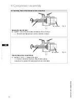
  To trap and collect leaked oil, the FK40 is fitted with an integrated 

leak oil trapping device with oil reservoir (P.6, Fig. 1).

 ATTENTION! After a compressor is replaced, the oil level must be checked again.  
     

If the level is too high, oil must be drained off (risk of oil impact,  


reduced performance of the air-conditioning system).

Содержание FK40/560 N

Страница 1: ...60 K FK40 655 K FK40 390 TK FK40 470 TK FK40 560 TK FK40 655 TK FKX40 390 N FKX40 470 N FKX40 560 N FKX40 655 N FKX40 390 K FKX40 470 K FKX40 560 K FKX40 655 K FKX40 390 TK FKX40 470 TK FKX40 560 TK F...

Страница 2: ...use of the compressor can lead to serious or fatal injury Observe the safety instructions contained in these instructions These instructions must be passed onto the end customer along with the unit in...

Страница 3: ...e inclination 4 3 V belt drive 4 4 Main bearing load 4 5 Electromagnetic coupling assembly 4 6 Pipe connections 4 7 Pipes 4 8 Operating the shut off valves 4 9 Operating mode of the lockable service c...

Страница 4: ...hines and as such call for heightened caution and care in handling The maximum permissible overpressure must not be exceeded even for testing purposes WARNING Risk of burns Depending on the operating...

Страница 5: ...Any other use of the compressor is prohibited The Bock refrigerating compressor named in the title is intended for installation in a machine within the EU according to the EU Directives 2006 42 EC Mac...

Страница 6: ...safety and efficiency are concerned Compact four cylinder compressor in V design Four capacity ranges Lightweight aluminum design Lubricating oil pump with oil pressure relief valve independent of rot...

Страница 7: ...ure side 4 Machine number 5 Factory filled oil type Fig 3 2 2 Name plate example 2 3 Type key example K specially for air conditioning N specially for air conditioning or normal cooling TK specially f...

Страница 8: ...we recommend the use of a thermal protection thermostat Accessories Chap 7 When capacity regulators are used the limits of application can move When operating in the vacuum range there is a danger of...

Страница 9: ...uction gas superheat K Suction gas superheat K Suction gas temperature C Suction gas temperature C Fig 4 Fig 5 20 30 50 70 80 20 10 10 0 20 30 t C o t C c 82 30 40 60 90 t 25 C oh toh 20 K R134a 20 30...

Страница 10: ...bereich reduzierte Sauggastemperatur FK R22 tc t0 toh Dtoh Verdampfungstemperatur C Verfl ssigungstemperatur C Sauggas berhitzung K Sauggastemperatur C Uneingeschr nkter Anwendungsbereich reduzierte S...

Страница 11: ...essor for transport damage before starting any work Fig 8 Fig 9 Transport and suspension unit on the eyebolt Fig 8 or direct on the discharge line valve Fig 9 Fittings e g pipe holders additional unit...

Страница 12: ...the magnetic field of the electromagnetic clutch the front bearing flange has a snug fit 148 h8 see Fig 12 To connect the magnetic field loosen the 4 cheese head screws M8 on the bearing flange see F...

Страница 13: ...inhibit oxidation products scale The pipe connections have stepped internal diameters so that pipes with standard millimetre and inch dimensions can be used The connection diameters of the shut off va...

Страница 14: ...on 2 2 Fig 17 Opening the shut off valve a Spindle 1 turn to the left counter clockwise as far as it will go Shut off valve fully opened service connection 2 closed Fig 18 Opening the service connecti...

Страница 15: ...compressor for transport damage 5 2 Pressure strength test DANGER Bursting The compressor must only be pressurised using nitrogen N2 Never pressurise with oxygen or other gases The maximum permissibl...

Страница 16: ...es The oil level must be visible in at least one sightglass ATTENTION Avoid overfilling the system with refrigerant To avoid shifts in concentration zeotropic refrigerant blends e g R407C must always...

Страница 17: ...especially important to ensuring fault free operation The complete refrigerant circuit must be correctly executed and clean inside Heavy shocks and vibrations to the shaft as well as continuous cycli...

Страница 18: ...alve is maintenance free However constant leakage can occur after blowing off due to abnormal operating conditions This leads to reduced performance and increases the compressed gas temperature In thi...

Страница 19: ...th the valid national regulations 6 Maintenance 6 5 Extract from the lubricants table The oil type charged as standard in the factory is marked on the name plate This oil type should be used as a pref...

Страница 20: ...ty regulated operation alters the gas speeds and pressure ratios of the refrigerating plant Adjust the suction line routing and dimensioningaccordingly donotsetthecontrolintervalstoocloseand do not le...

Страница 21: ...t of the driving unit kgm 2 Lubri cation Oil pump FK40 390 4 385 33 5 34 0 22 7 8 28 1 1 8 2 0 0 0043 Forced lubrication Rotation independent FK40 470 466 40 5 33 0 28 1 1 8 35 1 3 8 FK40 560 554 48 3...

Страница 22: ...onnections Dimensions in K Design Shaft end Centre of gravity Dimensions in mm Dimensions in mm Fig 20 Fig 21 169 ca 110 ca 170 M SV A SV1 A1 C E G 13 232 210 145 329 ca 370 4x ca 320 325 F DV B B1 L...

Страница 23: ...kable 7 16 UNF B Connection discharge side not lockable 1 8 NPTF B1 Connection discharge side lockable 7 16 UNF C Connection oil pressure safety switch OIL 1 8 NPTF D Connection oil pressure safety sw...

Страница 24: ...12100 2 EN 12693 EN 349 A partly completed machine may only be put into operation when it has been established that the machine into which the partly completed machine is to be installed conforms to t...

Страница 25: ...eichnet WARNUNG Dieses Symbol weist darauf hi dass ungenaues Befolgen oder Nichtbefolg von Anweisungen zu Sch den an Personen am Verdichter oder an der K lteanlage f h kann GEFAHR Dieses Symbol weist...

Страница 26: ...re than 50 countries Founded in 1881 the company is one of the largest providers of innovative equipment and process technology GEA Group is listed in the STOXX Europe 600 Index GEA Refrigeration Tech...

Отзывы: