background image

  D
 GB
  F
  E

25

09702-09.2013-DGbF

10

|

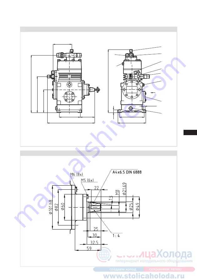
  Dimensions and connections F

Compressor type F2

Shaft end F2 

Fig. 23

Dimensions in mm

Fig. 24

Dimensions in mm

Dimensions for view X see page 32

Woodruff key

Cone

101

114

77

ca.255

123

195

310

ca.340

134

152

4xØ9

15

B1

B/L

B

DV

A1

SV

A

H/D1

K

F/G

X

Содержание F Series

Страница 1: ...H3 F5 NH3 F14 1166 F14 1366 F14 1166 NH3 F14 1366 NH3 F16 1751 F16 2051 F16 1751 NH3 F16 2051 NH3 FX2 FX3 FX4 FX5 FX14 1166 FX14 1366 FX16 1751 FX16 2051 engineering for a better world GEA Refrigeration Technologies Bock Compressors F F NH3 Assembly instructions ...

Страница 2: ... the compressor can lead to serious or fatal injury Observe the safety instructions contained in these instructions These instructions must be passed onto the end customer along with the unit in which the compres sor is installed GEA Bock GmbH 72636 Frickenhausen Manufacturer Contact GEA Bock GmbH Benzstraße 7 72636 Frickenhausen Germany Telephone 49 7022 9454 0 Fax 49 7022 9454 137 bock gea com w...

Страница 3: ...5 5 Laying suction and discharge lines 5 6 Operating the shut off valves 5 7 Operating mode of the lockable service connections 5 8 Drive 5 9 Oil sump heating standard by F4 F5 F14 and F16 6 Commissioning 18 6 1 Preparations for start up 6 2 Pressure resistance test 6 3 Leak test 6 4 Evacuation 6 5 Refrigerant charge 6 6 Shaft seal 6 7 Shaft seal change 6 8 Start up 6 9 Avoiding slugging 7 Mainten...

Страница 4: ...ious injury Indicates a dangerous situation which if not avoided may cause fairly severe or minor injury Indicates a situation which if not avoided may cause property damage Important information or tips on simplifying work WARNING Inadequately qualified personnel poses the risk of accidents the consequence being serious or fatal injury Work on compressors is therefore reserved for personnel with ...

Страница 5: ... and 30 vol in the air Due to the high ignition energy and temperature the risk of explosion however is rated as low So there are no special explosion protection measures are required However the national safety regulations accident prevention regulations technical regulations as well as specific regulations EN 378 etc must be observed NH3 steam is lighter than air and therefore disperses upwards ...

Страница 6: ... the basic compressor F Pistons with three ring assembly Con rod with additional oil supply oil to the small end Valve plate with optimised pressure unit Shut off valve with steel connector for welded joints All connections are designed as compression joints for steel pipes F14 NH3 and F16 NH3 with increased oil volume due to the higher base plate Special oil filling for NH3 Fuchs Reniso KC 68 Sho...

Страница 7: ...16 Fig 2 Suction shut off valve Valve plate Base plate Name plate Cylinder cover Discharge shut off valve Shaft seal Shaft end Compressor housing Fig 3 Transport eyelet Discharge shut off valve Cylinder cover Compressor housing Base plate Valve plate Suction shut off valve Leak oil drain hose Shaft seal Shaft end Transport eyelet ...

Страница 8: ...e Oil charge Series 1 2 3 4 5 6 FX16 2051 SE55 19 28 1 Type designation 2 Machine number 3 Rotation speed minimum with a corresponding displacement 4 Rotation speed maximum with a corresponding displacement 5 ND LP Max admissible operating pressure Suction side HD HP Max admissible operating pressure High pressure side 6 Oil type charged at factory Observe the limit of application diagrams GEA Boc...

Страница 9: ...ywhen operating near to the threshold When operating in the vacuum range there is a danger of air entering on the suction side This can cause chemical reactions a pressure rise in the condenser and an elevated compressed gas temperature Prevent the ingress of air at all costs The compressors are filled with the following oil type at the factory for R134a R404A R507 R407C FUCHS Reniso Triton SE 55 ...

Страница 10: ...F16 700 1800 rpm 3 3 Operating limits R134a Fig 6 R404A R507 Fig 7 R407C Fig 8 R22 Fig 9 Unlimited application range Reduced suction gas temperature Evaporating temperature C Condensing temperature C Suction gas superheat K Suction gas temperature C Maximum admissible operating pressure g High pressure side LP HP 1 19 28 bar 1 LP Low pressure HP High pressure ...

Страница 11: ...2 NH3 F3 NH3 960 1500 rpm F4 NH3 F5 NH3 500 1500 rpm F14 NH3 F16 NH3 700 1500 rpm Supplementary cooling necessary e g water cooled cylinder covers Unlimited application range Evaporating temperature C Condensing temperature C Suction gas superheat K Design for other areas on request Max permissible operating pressure LP HP 1 19 25 bar 1 LP Low pressure HP High pressure 15 Nh3 30 20 0 10 10 20 t C ...

Страница 12: ... as possible and prevent the ingress of air Check the compressor for transport damage before starting any work Fig 13 Fig 14 Fig 15 Fig 11 F E D 1 2 3 Transport and suspension unit on the eyebolt Fig 12 F14 to F16 or direct on the discharge line valve Fig 11 F2 to F5 WARNING Move compressors only with hoists that have adequate load bearing capacity Fittings e g pipe holders additional units etc on...

Страница 13: ... standard millimetre and inch dimensions can be used The connection diameters of the shut off valves are designed for maximum compressor output The required pipe cross section must be matched to the capacity The same applies for non return valves The required tightening torque for the flange connection is 60 Nm Fig 17 Stepped internal diameters 5 2 Maximum permissible inclination ATTENTION Poor lu...

Страница 14: ...talled pipes can cause cracks and tears the result being a loss of refrigerant A rule of thumb Always lay the first pipe section starting from the shut off valve downwards and parallel to the drive shaft Fig 18 Rigid Fixed point As short as possible Valve spindle seal Before opening or closing the shut off valve release the valve spindle seal by approx of a turn counter clockwise After activating ...

Страница 15: ...lly open and the service connection is closed The connection which is not lockable is provided for safety devices Fig 22 Opening the service connection Spindle 1 rotation to the right clockwise The service connection is then open and the shut off valve is also open The connection which is not lockable is provided for safety devices Service connection closed Service connection opened Connection blo...

Страница 16: ... pre tension according to the instructions issued by the V belt manufacturer Avoid belt fluttering Check belt pre tension after running in time Direct drive with shaft coupling Direct drive with shaft couplings demands highly precise aligning of compressor shaft and motor shaft Use the Bock shaft couplings WK and observe the enclosed assembly instructions CAUTION Mount suitable safeguards when dri...

Страница 17: ...eventually lead to compressor damage To prevent this the oil can be heated via an oil sump heater Operation Oil sump heater ON at standstill of the compressor Oil sump heater OFF during operation of the compressor Connection Oil sump heater must be connected via an auxiliary contact or parallel wired auxiliary contact of the motor contactor to a separate electric circuit 5 9 Oil sump heating WARNI...

Страница 18: ...ss as often as is required 6 2 Pressure strength test DANGER Bursting The compressor must only be pressurised using nitrogen N2 Never pressurise with oxygen or other gases The maximum permissible overpressure of the compressor must not be exceeded at any time during the testing process see name plate data Do not mix any refrigerant with the nitrogen as this could cause the ignition limit to shift ...

Страница 19: ...ENTION Failure to observe the following instructions can cause loss of refrigerant and damage to the shaft seal INFO The shaft seal seals and lubricates with oil An oil leakage of 0 05 ml per operating hour is therefore normal This applies particularly during the run in phase 200 300 h The compressor types F14 and F16 are equipped with a leak oil drain hose see chapter 10 and 11 The leak oil is co...

Страница 20: ...ATTENTION If larger quantities of oil have to be topped up there is a risk of oil hammer effects If this is the case check the oil return 6 9 Avoiding slugging ATTENTION Slugging can damage the compressor and cause coolant to leak To prevent slugging The complete refrigeration system must be properly designed All components must be compatibly rated with each other with regard to output particularl...

Страница 21: ...ed in the factory not mandatory In field installations or operating in the application limit range first oil change after approx 100 200 operating hours then approx every 3 years or 10 000 12 000 operating hours for NH3 plants oil change every year or every 5 000 operating hours Dispose of old oil according to the regulations observe national regulations Annual checks Oil level tightness running n...

Страница 22: ...e original Bock spare parts 7 4 Spare parts recommendation NH3 NH3 7 7 Decommissioning 7 Maintenance Refrigerant Bock series oil grades Recommended alternatives HFKW e g R134a R404A R507 R407C Fuchs Reniso Triton SE 55 FUCHS Reniso Triton SEZ 32 ICI Emkarate RL 32 H S MOBIL Arctic EAL 32 SHELL Clavus R 32 HFCKW e g R22 Fuchs Reniso SP 46 FUCHS Reniso z B KM HP SP 32 SHELL Clavus SD 22 12 TEXACO Ca...

Страница 23: ...rpm F2 2 10 50 12 60 18 16 I 5 8 16 I 5 8 0 8 960 1800 F3 20 30 24 30 28 22 I 7 8 28 I 1 1 8 1 5 F4 4 40 50 48 60 51 28 I 1 1 8 35 I 1 3 8 2 6 500 1800 F5 73 70 88 40 85 35 I 1 3 8 2 x 35 I 1 3 8 3 8 F14 1166 F14 1366 4 101 40 121 70 119 00 142 80 149 42 I 1 5 8 54 I 2 1 8 3 8 700 1800 F16 1751 F16 2051 6 152 20 182 60 178 40 214 10 175 42 I 1 5 8 54 I 2 1 8 5 0 700 1800 Type for soldering joint i...

Страница 24: ...ge line DV Suction line SV m 3 h kg mm mm ltr rpm F2 NH 3 2 10 50 18 18 18 0 8 960 1500 F3 NH 3 20 30 28 25 30 1 5 F4 NH 3 4 40 50 51 30 38 2 6 500 1500 F5 NH 3 73 70 85 38 2 x 38 3 8 F14 1166 NH 3 F14 1366 NH 3 4 101 50 118 90 158 49 60 6 3 700 1500 F16 1751 NH 3 F16 2051 NH 3 6 152 20 178 40 183 49 60 7 5 700 1500 Type for soldering joint in standard design ...

Страница 25: ...sions and connections F Compressor type F2 Shaft end F2 Fig 23 Dimensions in mm Fig 24 Dimensions in mm Dimensions for view X see page 32 Woodruff key Cone 101 114 77 ca 255 123 195 310 ca 340 134 152 4xØ9 15 B1 B L B DV A1 SV A H D1 K F G X ...

Страница 26: ...nd connections F Compressor type F3 Shaft end F3 Fig 25 Dimensions in mm Fig 26 Dimensions in mm Dimensions for view X see page 32 Woodruff key Cone 118 130 96 5 ca 315 90 135 175 200 4xØ9 230 17 135 360 ca 400 DV B L A A1 SV C E D D1 H K F G B1 X ...

Страница 27: ...s and connections F Compressor type F4 Shaft end F4 Fig 27 Dimensions in mm Fig 28 Dimensions in mm Dimensions for view X see page 32 Woodruff key Cone 4x 11 ca 305 170 ca 455 130 ca 225 K F J H D B DV B1 L SV A A1 C E D1 395 210 240 25 ca 430 X ...

Страница 28: ...nd connections F Compressor type F5 Shaft end F5 Fig 29 Dimensions in mm Fig 30 Dimensions in mm Dimensions for view X see page 32 Woodruff key Cone 4xØ11 150 169 ca 470 ca 465 D D1 H 25 170 340 430 240 270 246 ca 355 B1 L B DV SV A A1 C E K F J X ...

Страница 29: ...nd F14 Fig 31 Dimensions in mm Dimensions in with elevated base plate Woodruff key Cone 362 124 4xØ13 5 290 320 ca 510 560 448 498 432 482 180 230 20 ca 415 121 5 290 342 ca 530 X Y Y SV DV L A B2 D B H D1 A1 P B1 B C E K F J ÖV1 Fig 32 Dimensions in mm Dimensions for view X Y see page 32 Leak oil drain hose ...

Страница 30: ...nd F16 Fig 33 Dimensions in mm Dimensions in with elevated base plate Woodruff key Cone 290 143 5 290 B A1 B1 B C K F J ÖV1 P D1 H E Y Y 520 20 320 452 502 200 250 470 ca 515 ca 535 585 4x 13 5 A SV DV L B2 D X 363 342 ca 580 170 Fig 34 Dimensions in mm Dimensions for view X Y see page 32 Leak oil drain hose ...

Страница 31: ...6 UNF D1 Connection oil return from oil separator 1 8 NPTF 1 8 NPTF 1 8 NPTF 1 8 NPTF 5 8 UNF 5 8 UNF E Connection oil pressure gauge 1 8 NPTF 7 16 UNF 7 16 UNF 7 16 UNF 7 16 UNF F Oil drain plug R 3 8 M22 x 1 5 M22 x 1 5 M22 x 1 5 M26 x 1 5 M26 x 1 5 H Oil charge plug 1 8 NPTF 1 8 NPTF M22 x 1 5 M22 x 1 5 M22 x 1 5 M22 x 1 5 J Oil sump heater R 3 8 1 M22 x 1 5 1 M22 x 1 5 M22 x 1 5 M22 x 1 5 M22 ...

Страница 32: ...imensions and connections Connection facilities Operation with oil level regulator Fig 35 Operation with common oil gas balance pipe example 3 compressors in parallel Art Nr 80462 BOCK adapter for oil level regulator fits the makes ESK AC R CARLY 3 hole fastener on the side of the oil level regulator 4 hole fastener on the side of the compressor Art Nr 80463 BOCK adapter for oil gas regulator sing...

Страница 33: ...H3 Shaft end F2 NH3 Fig 36 Dimensions in mm Fig 37 Dimensions in mm Dimensions for view X see page 40 Woodruff key Cone 4xØ9 134 152 15 123 ca 330 105 95 114 77 ca 265 300 195 B1 B L DV SV A1 H D1 K F G X 4xØ9 134 152 15 123 ca 330 105 95 114 77 ca 265 300 195 B1 B L DV SV A1 H D1 K F G X ...

Страница 34: ...ections F NH3 Compressor type F3 NH3 Shaft end F3 NH3 Fig 38 Dimensions in mm Fig 39 Dimensions in mm Dimensions for view X see page 40 Woodruff key Cone 130 96 5 ca 345 175 200 4xØ9 118 120 75 230 17 135 ca 365 ca 390 B L SV C E D D1 H K F G DV B1 A A1 X ...

Страница 35: ...tände durch den Der Lieferant muß sicherstellen dass die Ware in einwandfreiem Zustand angeliefert wird Korrosions B X 213 130 169 ca 450 H DV B1 L SV A A1 C E K F G D1 D 240 210 170 ca 425 25 398 11 4x ca 305 mm Offener Verdichter Open type compressor Compresseur ouvert erve de toutes modifikations mm n in mm Teile Nr 09877 o change without notice V Schneidringverschraubung ns du bout d arbre sur...

Страница 36: ...5 NH3 Fig 42 Dimensions in mm Fig 43 Dimensions in mm Dimensions for view X see page 40 Woodruff key Cone 4xØ11 150 169 ca 470 ca 485 B 240 270 ca 355 B1 DV 246 L A1 H D1 D 25 170 347 464 SV C E K F G A X 4xØ11 150 169 ca 470 ca 485 B 240 270 ca 355 B1 DV 246 L A1 H D1 D 25 170 347 464 SV C E K F G A X ...

Страница 37: ...s in mm Woodruff key Cone 290 121 5 342 ca 530 DV L A B2 D SV 4xØ13 5 290 320 A1 B1 B E C K G F ÖV1 B H D1 362 124 ca 415 230 482 498 ca 560 20 X Y Y 290 121 5 342 ca 530 DV L A B2 D SV 4xØ13 5 290 320 A1 B1 B E C K G F ÖV1 B H D1 362 124 ca 415 230 482 498 ca 560 20 X Y Y Fig 45 Dimensions in mm Dimensions for view X Y see page 40 Leak oil drain hose ...

Страница 38: ...mostat Connection thermal protection thermostat Raccord de thermostat de protection thermique Zoll 1 8 NPTF ÖV 1 Typ Teile Nr F16 1751 NH3 11708 F16 2051 NH3 11713 290 143 5 290 A SV DV L X 342 363 170 ca 580 F16 4 3 5 6 7 Abnehmer oder Dritte ist nicht gestattet Numéro de plan L und Anschluss L in B geändert arbeitet Erstellung Explosionsbild Übernahme auf 3D Tol Ang DIN ISO 2768 mK Maß Passung L...

Страница 39: ...D Connection oil pressure safety switch LP Ø 10 V 1 Ø 6 V 1 Ø 6 V 1 Ø 6 V 1 Ø 6 V 1 D1 Connection oil return from oil separator Ø 10 V 1 Ø 10 V 1 Ø 10 V 1 Ø 10 V 1 Ø 10 V 1 Ø 10 V 1 E Connection oil pressure gauge Ø 6 V 1 Ø 6 V 1 Ø 6 V 1 Ø 6 V 1 Ø 6 V 1 F Oil drain plug R 3 8 M22 x 1 5 M22 x 1 5 M22 x 1 5 M26 x 1 5 M26 x 1 5 G Oil sump heater plug R 3 8 M22 x 1 5 M22 x 1 5 M22 x 1 5 M22 x 1 5 M22 ...

Страница 40: ...llel operation Position view X F2 NH3 F3 NH3 F4 NH3 F5 NH3 F14 NH3 F16 NH3 4 hole oil sight glass Position view Y F14 NH3 F16 NH3 Second oil sight glass can be attached as an option available as original equipment only 50 45 90 4 x M6 10 mm deep mm Fig 48 11 Dimensions and connections F NH3 ...

Страница 41: ...08 and the corresponding standards referenced A partly completed machine may only be put into operation when it has been established that the machine into which the partly completed machine is to be installed conforms to the regulations of the Machinery Directive 2006 42 EC The manufacturer undertakes to transmit electronically the special documentation required by individual states for partly com...

Страница 42: ... specialist wholesaler and or our representative The Bock service team can be contacted by phone with a toll free hotline 00 800 800 000 88 or via e mail bock gea com Yours faithfully GEA Bock GmbH Benzstraße 7 72636 Frickenhausen Germany We also provide information on the Internet at www bock de For example under the Documentation link you will find Technical information Product information Produ...

Страница 43: ...D GB F E 43 09702 09 2013 DGbF ...

Страница 44: ... 0 Fax 49 7022 9454 137 bock gea com www bock de We live our values Excellence Passion Integrity Responsibility GEA versity GEA Group is a global engineering company with multi billion euro sales and operations in more than 50 countries Founded in 1881 the company is one of the largest providers of innovative equipment and process technology GEA Group is listed in the STOXX Europe 600 index ...

Отзывы: