


D
GB
F
E
3
96458-03.2019-DGb
Contents
Page
3
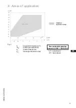
Areas of application
8
3.1 Refrigerants
3.2 Oil charge
3.3 Limits of application
4
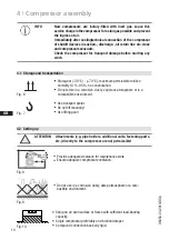
Compressor assembly
10
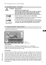
4.1 Storage and transportation
4.2 Setting up
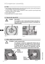
4.3 Connecting the pipelines - solder system
4.4 Connecting the pipelines - cutting ring system
4.5 Pipes
4.6 Flange shut-off valves (HP/LP)
4.7 Option: cutting ring screw joint (HP/LP)
4.8 Laying suction and pressure lines
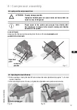
4.9 Operating the shut-off valves
4.10 Operating mode of the lockable service connections
4.11 Suction pipe filter
5
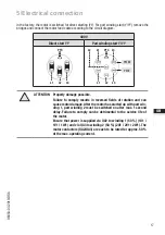
Electrical connection
15
5.1 Information for contactor and motor contactor selection
5.2 Standard motor, designed for direct or part winding start
5.3 Basic circuit diagram for part winding start
5.4 Electronic trigger unit INT69 G
5.5 Connection of the electronic trigger unit INT69 G
5.6 Functional test of the electronic trigger unit INT69 G
5.7 Oil sump heater
6 Commissioning
22
6.1 Preparations for start-up
6.2 Pressure strength test
6.3 Leak test
6.4 Evacuation
6.5 Refrigerant charge
6.6 Start-up
6.7 Pressure switch
6.8 Decompression valves
6.9 Avoiding slugging
6.10 Filter dryer
7 Maintenance
26
7.1 Preparation
7.2 Work to be carried out
7.3 Accessories
7.4 Spare parts recommendation
7.5 Lubricants
7.6 Decommissioning
8
Technical data
28
9
Dimensions and connections
29
10 Declaration of installation
31
11 Service
32
Содержание Bock HGX2 CO2 T Series
Страница 33: ...D GB F E 33 96458 03 2019 DGb ...


