© GE All Rights Reserved
7
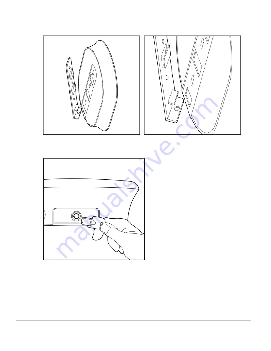
Step 4:
Slide WattStation unit onto the mounting bracket, ensuring that the opening in the back
plate bracket aligns with the tab on the wall mount bracket
Step 5:
Lock the WattStation unit onto the mounting bracket using the provided key


