GE UVD-XP3DNR(-P) Скачать руководство пользователя страница 15


• 

Digital tilt.

 Adjust where the camera zooms upon alarm. Move the slider to the 

left to tilt down, and to the right to tilt up. 
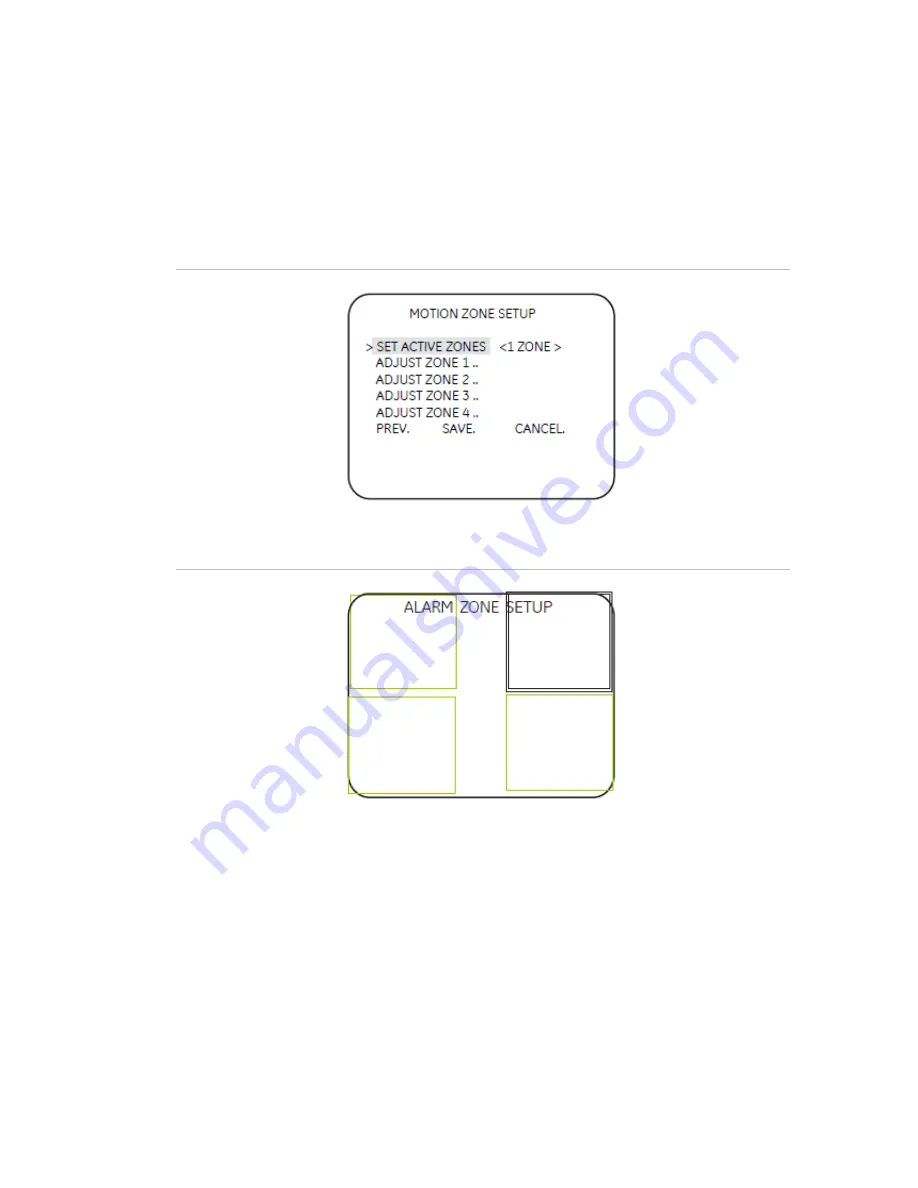
Setup motion zone 

The camera will monitor for motion in the area defined in the boxes defined in this 
submenu (Figure 12 below). When motion is detected in this area, the camera issues 
an alarm and zooms in.


Figure 12: Motion zone setup 


Figure 13: Alarm zone setup 


To set up the alarm zone, do the following: 
1.   Choose one of the options Adjust Zone 1/2/3/4 from the Setup Motion Zone menu 

(Figure 12 above). The selected zone will have a thick border and be highlighted in 
white. Press the arrow keys to change the selected zone (Figure 14). 

2.  Press Enter. The selected zone becomes green. Press the arrow keys to increase 

the zone area. 

3.  Press Enter. The selected zone becomes red. Press the arrow keys to shrink the 

zone area. 

4.   Press Enter for a few moments to leave the Alarm Zone Setup menu and return to 

Motion Zone Setup menu. 

UVD-XP3DNR(-P) Camera User Manual 

13 

Содержание UVD-XP3DNR(-P)

Страница 1: ...GE Security REV 01 00 ISS 02SEP09 UVD XP3DNR P Camera User Manual...

Страница 2: ...r visit us online at www gesecurity com FCC compliance This equipment has been tested and found to comply with the limits for a Class A digital device pursuant to part 15 of the FCC Rules These limits...

Страница 3: ...d 6 Installation 7 Cable connection 7 Camera installation 7 Angle adjustment 7 Focus adjustment 8 Connect the monitor 8 Programming 9 Navigation 9 Main menu 9 Presets menu 10 Setup menu 10 Viewing men...

Страница 4: ......

Страница 5: ...systems and components and a basic knowledge of electrical wiring and low voltage electrical connections Note A qualified service person complying with all applicable codes should perform all require...

Страница 6: ...se the following guidelines Program as many camera settings as possible before mounting the camera Take appropriate safety precautions while completing programming after installation Always use a 12 V...

Страница 7: ...e Camera body OSD control pad Video monitor output Figure 3 shows the monitor output components Figure 2 Monitor output cable A Monitor output BNC B Monitor output RCA Plug the monitor output RCA into...

Страница 8: ...Up Moves the cursor upward to select an item Left Moves the cursor left to select or adjust the parameters of the selected item Right Moves the cursor to the right to select or adjust the parameters...

Страница 9: ...amera gives the following information Red cable Power in Black cable Power in White cable Video out Black cable Video ground Note For AC24V or DC12V Black or Red may be used for ground Camera installa...

Страница 10: ...ired focus 6 Tighten the focus ring thumbscrew Figure 5 Zoom and focus adjustment Zoom ring thumbscrew for VA2 and focus ring for VA9 lens Focus ring thumbscrew for VA2 and zooming ring for VA9 lens C...

Страница 11: ...on the control pad to select the different options available for the item You can return to the previous menu from any of the menus except the Main menu by selecting the Previous page option Main menu...

Страница 12: ...e used with a 24 VAC power supply NTSC50Hz This mode uses a DC iris lens to reduce phase roll under fluorescent lights This mode will not function correctly with a manual iris lens Setup menu The Setu...

Страница 13: ...uorescent lights LL Line lock Used to sync video for AC power input so that the sync matches the frequency of the power input to eliminate the roll caused by fluorescent lights Figure 10 Figure 9 Line...

Страница 14: ...is zoomed tilted and panned to the area setup in Setup alarm zone Figure 11 Motion detection menu Motion detection menu The Motion detection menu Figure 11 above provides the following options Motion...

Страница 15: ...set up the alarm zone do the following 1 Choose one of the options Adjust Zone 1 2 3 4 from the Setup Motion Zone menu Figure 12 above The selected zone will have a thick border and be highlighted in...

Страница 16: ...u Exposure menu The Exposure menu Figure 15 below provides the following options AGC medium high custom or low The camera automatically adjusts the image quality in low light conditions AE preferences...

Страница 17: ...In PTL mode you can set a specific white balance Figure 16 White balance menu Save restore menu The Save restore menu Figure 17 below provides the following options Save user settings Saves all curren...

Страница 18: ...Menu Map...

Отзывы: