2-4
L90 Line Current Differential System
GE Multilin
2.1 INTRODUCTION
2 PRODUCT DESCRIPTION
2
•
Breaker arcing current
MONITORING:
•
Oscillography of current, voltage, FlexLogic operands, and digital signals (1
128 cycles to 31
8 cycles configurable)
•
Events recorder: 1024 events
•
Fault locator
METERING:
•
Actual 87L remote phasors, differential current, channel delay, and channel asymmetry at all line terminals of line cur-
rent differential protection
•
Line current, voltage, real power, reactive power, apparent power, power factor, and frequency
COMMUNICATIONS:
•
Front panel RS232 port: 19.2 kbps
•
Rear RS485 port: up to 115 kbps
•
Rear 100Base-FX Ethernet port supporting the IEC 61850 protocol
2.1.3 ORDERING
a) OVERVIEW
The L90 is available as a 19-inch rack horizontal mount or reduced-size (¾) vertical unit and consists of the following mod-
ules: power supply, CPU, CT/VT, digital input and output, transducer input and output, and inter-relay communications.
Each of these modules can be supplied in a number of configurations specified at the time of ordering. The information
required to completely specify the relay is provided in the following tables (see chapter 3 for full details of relay modules).
Order codes are subject to change without notice. See the GE Multilin ordering page at
http://www.gedigitalenergy.com/multilin/order.htm
for the latest ordering options.
The order code structure is dependent on the mounting option (horizontal or vertical) and the type of CT/VT modules (regu-
lar CT/VT modules or the HardFiber
TM
modules). The order code options are described in the following sub-sections.
b) ORDER CODES WITH TRADITIONAL CTS AND VTS
The order codes for the horizontal mount units with traditional CTs and VTs are shown below.
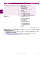
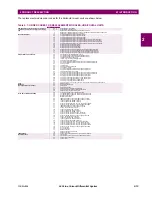
Table 2–3: L90 ORDER CODES (HORIZONTAL UNITS)
L90
-
*
**
- *
*
* - F
**
- H
**
- L
**
- N
**
- S
**
- U
**
- W/X
**
Full Size Horizontal Mount
BASE UNIT
L90
|
|
|
|
|
|
|
|
|
|
|
|
Base Unit
CPU
T
|
|
|
|
|
|
|
|
|
|
|
RS485 and Three Multi-mode fiber 100Base-FX (SFP with LC)
U
|
|
|
|
|
|
|
|
|
|
|
RS485 and Two Multi-mode fiber 100Base-FX (SFP with LC), One 10/100Base-T (SFP with RJ45)
V
|
|
|
|
|
|
|
|
|
|
|
RS485 and Three 10/100Base-T (SFP with RJ45)
SOFTWARE
00
|
|
|
|
|
|
|
|
|
|
No software options
02
|
|
|
|
|
|
|
|
|
|
Breaker-and-a-half
03
|
|
|
|
|
|
|
|
|
|
IEC 61850
05
|
|
|
|
|
|
|
|
|
|
Breaker-and-a-half and IEC 61850
06
|
|
|
|
|
|
|
|
|
|
Phasor measurement unit (PMU)
07
|
|
|
|
|
|
|
|
|
|
IEC 61850 and PMU
08
|
|
|
|
|
|
|
|
|
|
Breaker-and-a-half and PMU
09
|
|
|
|
|
|
|
|
|
|
Breaker-and-a-half, IEC 61850, and PMU
24
|
|
|
|
|
|
|
|
|
|
In-zone transformer protection
25
|
|
|
|
|
|
|
|
|
|
In-zone transformer protection and IEC 61850
26
|
|
|
|
|
|
|
|
|
|
In-zone transformer protection and PMU
27
|
|
|
|
|
|
|
|
|
|
In-zone transformer protection, IEC 61850, and PMU
80
|
|
|
|
|
|
|
|
|
|
In-zone transformer and Breaker-and-a-half
81
|
|
|
|
|
|
|
|
|
|
In-zone transformer, IEC 61850, and Breaker-and-a-half
82
|
|
|
|
|
|
|
|
|
|
In-zone transformer, Breaker-and-a-half, and PMU
83
|
|
|
|
|
|
|
|
|
|
In-zone transformer, IEC 61850, Breaker-and-a-half, and PMU
A0
|
|
|
|
|
|
|
|
|
|
CyberSentry Lvl 1
A2
|
|
|
|
|
|
|
|
|
|
CyberSentry Lvl 1 and Breaker-and-a-half
A3
|
|
|
|
|
|
|
|
|
|
CyberSentry Lvl 1 and IEC 61850
A5
|
|
|
|
|
|
|
|
|
|
CyberSentry Lvl 1, IEC 61850, and Breaker-and-a-half
A6
|
|
|
|
|
|
|
|
|
|
CyberSentry Lvl 1 and PMU
A7
|
|
|
|
|
|
|
|
|
|
CyberSentry Lvl 1, IEC 61850, and PMU
A8
|
|
|
|
|
|
|
|
|
|
CyberSentry Lvl 1, PMU, and Breaker-and-a-half
A9
|
|
|
|
|
|
|
|
|
|
CyberSentry Lvl 1, IEC 61850, PMU, and Breaker-and-a-half
AO
|
|
|
|
|
|
|
|
|
|
CyberSentry Lvl 1 and In-zone transformer protection
AP
|
|
|
|
|
|
|
|
|
|
CyberSentry Lvl 1, IEC 61850, and In-zone transformer protection
AQ
|
|
|
|
|
|
|
|
|
|
CyberSentry Lvl 1, PMU, and In-zone transformer protection
AR
|
|
|
|
|
|
|
|
|
|
CyberSentry Lvl 1, IEC 61850, PMU, and In-zone transformer protection
B0
|
|
|
|
|
|
|
|
|
|
IEEE 1588
B2
|
|
|
|
|
|
|
|
|
|
IEEE 1588 and Breaker-and-a-half
B3
|
|
|
|
|
|
|
|
|
|
IEEE 1588 and IEC 61850
B5
|
|
|
|
|
|
|
|
|
|
IEEE 1588, IEC 61850, and Breaker-and-a-half
B6
|
|
|
|
|
|
|
|
|
|
IEEE 1588 and PMU
B7
|
|
|
|
|
|
|
|
|
|
IEEE 1588, IEC 61850, and PMU
B8
|
|
|
|
|
|
|
|
|
|
IEEE 1588, PMU, and Breaker-and-a-half
B9
|
|
|
|
|
|
|
|
|
|
IEEE 1588, IEC 61850, PMU, and Breaker-and-a-half
BO
|
|
|
|
|
|
|
|
|
|
IEEE 1588 and In-zone transformer protection
BP
|
|
|
|
|
|
|
|
|
|
IEEE 1588, IEC 61850, and In-zone transformer protection
BQ
|
|
|
|
|
|
|
|
|
|
IEEE 1588, PMU, and In-zone transformer protection
BR
|
|
|
|
|
|
|
|
|
|
IEEE 1588, IEC 61850, PMU, and In-zone transformer protection
C0
|
|
|
|
|
|
|
|
|
|
Parallel Redundancy Protocol (PRP)
NOTE
Содержание UR Series L90
Страница 14: ...xiv L90 Line Current Differential System GE Multilin 0 1 BATTERY DISPOSAL 0 BATTERY DISPOSAL 0 ...
Страница 68: ...2 34 L90 Line Current Differential System GE Multilin 2 4 SPECIFICATIONS 2 PRODUCT DESCRIPTION 2 ...
Страница 138: ...4 30 L90 Line Current Differential System GE Multilin 4 3 FACEPLATE INTERFACE 4 HUMAN INTERFACES 4 ...
Страница 604: ...9 58 L90 Line Current Differential System GE Multilin 9 6 FAULT LOCATOR 9 THEORY OF OPERATION 9 ...
Страница 652: ...A 16 L90 Line Current Differential System GE Multilin A 1 PARAMETER LISTS APPENDIX A A ...
Страница 772: ...B 120 L90 Line Current Differential System GE Multilin B 4 MEMORY MAPPING APPENDIX B B ...
Страница 802: ...C 30 L90 Line Current Differential System GE Multilin C 7 LOGICAL NODES APPENDIX C C ...
Страница 812: ...D 10 L90 Line Current Differential System GE Multilin D 1 IEC 60870 5 104 APPENDIX D D ...
Страница 824: ...E 12 L90 Line Current Differential System GE Multilin E 2 DNP POINT LISTS APPENDIX E E ...
Страница 834: ...F 10 L90 Line Current Differential System GE Multilin F 3 WARRANTY APPENDIX F F ...
Страница 846: ...xii L90 Line Current Differential System GE Multilin INDEX ...


