GE Multilin
C70 Capacitor Bank Protection and Control System
5-61
5 SETTINGS
5.2 PRODUCT SETUP
5
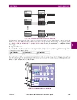
Figure 5–16: DUAL-CHANNEL CLOSED LOOP (DUAL-RING) CONFIGURATION
In the above application, the following settings should be applied. For UR-series IED 1:
DIRECT OUTPUT DEVICE ID:
“1”
DIRECT I/O CH1 RING CONFIGURATION:
“Yes”
DIRECT I/O CH2 RING CONFIGURATION:
“Yes”
For UR-series IED 2:
DIRECT OUTPUT DEVICE ID:
“1”
DIRECT I/O CH1 RING CONFIGURATION:
“Yes”
DIRECT I/O CH2 RING CONFIGURATION:
“Yes”
For UR-series IED 3:
DIRECT OUTPUT DEVICE ID:
“1”
DIRECT I/O CH1 RING CONFIGURATION:
“Yes”
DIRECT I/O CH2 RING CONFIGURATION:
“Yes”
In this configuration the following delivery times are expected (at 128 kbps) if both the rings are healthy:
IED 1 to IED 2: 0.2 of power system cycle;
IED 1 to IED 3: 0.2 of power system cycle;
IED 2 to IED 3: 0.2 of power system cycle.
The two communications configurations could be applied to both permissive and blocking schemes. Speed, reliability and
cost should be taken into account when selecting the required architecture.
b) CRC ALARM CH1(2)
PATH: SETTINGS
Ö
PRODUCT SETUP
ÖØ
DIRECT I/O
ÖØ
CRC ALARM CH1(2)
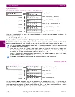
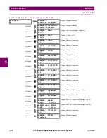
The C70 checks integrity of the incoming direct input and output messages using a 32-bit CRC. The CRC alarm function is
available for monitoring the communication medium noise by tracking the rate of messages failing the CRC check. The
monitoring function counts all incoming messages, including messages that failed the CRC check. A separate counter adds
up messages that failed the CRC check. When the failed CRC counter reaches the user-defined level specified by the
CRC
ALARM CH1 THRESHOLD
setting within the user-defined message count
CRC ALARM 1 CH1 COUNT
, the
DIR IO CH1 CRC ALARM
FlexLogic™ operand is set.
When the total message counter reaches the user-defined maximum specified by the
CRC ALARM CH1 MESSAGE COUNT
set-
ting, both the counters reset and the monitoring process is restarted.
CRC ALARM CH1
CRC ALARM CH1
FUNCTION: Disabled
Range: Enabled, Disabled
MESSAGE
CRC ALARM CH1
MESSAGE COUNT: 600
Range: 100 to 10000 in steps of 1
MESSAGE
CRC ALARM CH1
THRESHOLD: 10
Range: 1 to 1000 in steps of 1
MESSAGE
CRC ALARM CH1
EVENTS: Disabled
Range: Enabled, Disabled
842715A1.CDR
UR IED 1
TX1
RX2
TX2
RX1
UR IED 2
RX2
TX1
RX1
TX2
UR IED 3
RX1
TX2
TX1
RX2
Содержание UR Series C70
Страница 2: ......
Страница 10: ...x C70 Capacitor Bank Protection and Control System GE Multilin TABLE OF CONTENTS ...
Страница 30: ...1 20 C70 Capacitor Bank Protection and Control System GE Multilin 1 5 USING THE RELAY 1 GETTING STARTED 1 ...
Страница 124: ...4 30 C70 Capacitor Bank Protection and Control System GE Multilin 4 3 FACEPLATE INTERFACE 4 HUMAN INTERFACES 4 ...
Страница 344: ...5 220 C70 Capacitor Bank Protection and Control System GE Multilin 5 10 TESTING 5 SETTINGS 5 ...
Страница 396: ...8 18 C70 Capacitor Bank Protection and Control System GE Multilin 8 3 ENERVISTA SECURITY MANAGEMENT SYSTEM 8 SECURITY 8 ...
Страница 414: ...9 18 C70 Capacitor Bank Protection and Control System GE Multilin 9 1 OVERVIEW 9 THEORY OF OPERATION 9 ...
Страница 436: ...10 22 C70 Capacitor Bank Protection and Control System GE Multilin 10 4 SETTING EXAMPLE 10 APPLICATION OF SETTINGS 10 ...
Страница 547: ...GE Multilin C70 Capacitor Bank Protection and Control System B 79 APPENDIX B B 4 MEMORY MAPPING B ...
Страница 548: ...B 80 C70 Capacitor Bank Protection and Control System GE Multilin B 4 MEMORY MAPPING APPENDIXB B ...
Страница 586: ...D 10 C70 Capacitor Bank Protection and Control System GE Multilin D 1 OVERVIEW APPENDIXD D ...
Страница 598: ...E 12 C70 Capacitor Bank Protection and Control System GE Multilin E 2 DNP POINT LISTS APPENDIXE E ...

