GE Multilin
F35 Multiple Feeder Protection System
5-137
5 SETTINGS
5.5 FLEXLOGIC
5
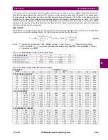
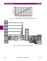
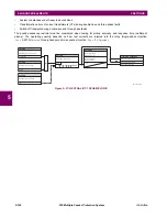
Figure 5–49: FLEXELEMENT SCHEME LOGIC
The
FLEXELEMENT 1 +IN
setting specifies the first (non-inverted) input to the FlexElement. Zero is assumed as the input if
this setting is set to “Off”. For proper operation of the element at least one input must be selected. Otherwise, the element
will not assert its output operands.
This
FLEXELEMENT 1 –IN
setting specifies the second (inverted) input to the FlexElement. Zero is assumed as the input if
this setting is set to “Off”. For proper operation of the element at least one input must be selected. Otherwise, the element
will not assert its output operands. This input should be used to invert the signal if needed for convenience, or to make the
element respond to a differential signal such as for a top-bottom oil temperature differential alarm. The element will not
operate if the two input signals are of different types, for example if one tries to use active power and phase angle to build
the effective operating signal.
The element responds directly to the differential signal if the
FLEXELEMENT 1 INPUT MODE
setting is set to “Signed”. The ele-
ment responds to the absolute value of the differential signal if this setting is set to “Absolute”. Sample applications for the
“Absolute” setting include monitoring the angular difference between two phasors with a symmetrical limit angle in both
directions, monitoring power regardless of its direction, or monitoring a trend.
The element responds directly to its operating signal – as defined by the
FLEXELEMENT 1 +IN
,
FLEXELEMENT 1 –IN
and
FLEX-
ELEMENT 1 INPUT MODE
settings – if the
FLEXELEMENT 1 COMP MODE
setting is set to “Level”. The element responds to the
rate of change of its operating signal if the
FLEXELEMENT 1 COMP MODE
setting is set to “Delta”. In this case the
FLEXELE-
MENT 1 dt UNIT
and
FLEXELEMENT 1 dt
settings specify how the rate of change is derived.
The
FLEXELEMENT 1 DIRECTION
setting enables the relay to respond to either high or low values of the operating signal. The
following figure explains the application of the
FLEXELEMENT 1 DIRECTION
,
FLEXELEMENT 1 PICKUP
and
FLEXELEMENT 1 HYS-
TERESIS
settings.
842004A4.CDR
FLEXELEMENT 1
FUNCTION:
SETTING
Enabled = 1
SETTINGS
FLEXELEMENT 1 INPUT MODE:
FLEXELEMENT 1 COMP MODE:
FLEXELEMENT 1 DIRECTION:
FLEXELEMENT 1 PICKUP:
FLEXELEMENT 1 dt UNIT:
FLEXELEMENT 1 dt:
RUN
FLEXELEMENT 1 +IN:
SETTINGS
Actual Value
FLEXLOGIC OPERANDS
FxE 1 DPO
FxE 1 OP
FxE 1 PKP
FLEXELEMENT 1 -IN:
Actual Value
+
-
FlexElement 1 OpSig
ACTUAL VALUE
FLEXELEMENT 1 BLK:
SETTING
Off = 0
AND
t
PKP
t
RST
SETTINGS
FLEXELEMENT 1 RST
DELAY:
FLEXELEMENT 1 PKP
DELAY:
FLEXELEMENT 1 INPUT
HYSTERESIS:
Содержание UR F35 Series
Страница 10: ...x F35 Multiple Feeder Protection System GE Multilin TABLE OF CONTENTS ...
Страница 30: ...1 20 F35 Multiple Feeder Protection System GE Multilin 1 5 USING THE RELAY 1 GETTING STARTED 1 ...
Страница 366: ...5 238 F35 Multiple Feeder Protection System GE Multilin 5 10 TESTING 5 SETTINGS 5 ...
Страница 396: ...6 30 F35 Multiple Feeder Protection System GE Multilin 6 5 PRODUCT INFORMATION 6 ACTUAL VALUES 6 ...
Страница 412: ...8 4 F35 Multiple Feeder Protection System GE Multilin 8 1 FAULT LOCATOR 8 THEORY OF OPERATION 8 ...
Страница 426: ...10 12 F35 Multiple Feeder Protection System GE Multilin 10 6 DISPOSAL 10 MAINTENANCE 10 ...
Страница 454: ...A 28 F35 Multiple Feeder Protection System GE Multilin A 1 PARAMETER LISTS APPENDIX A A ...
Страница 608: ...E 10 F35 Multiple Feeder Protection System GE Multilin E 1 IEC 60870 5 104 PROTOCOL APPENDIX E E ...
Страница 620: ...F 12 F35 Multiple Feeder Protection System GE Multilin F 2 DNP POINT LISTS APPENDIX F F ...
Страница 630: ...H 8 F35 Multiple Feeder Protection System GE Multilin H 3 WARRANTY APPENDIX H H ...
Страница 640: ...x F35 Multiple Feeder Protection System GE Multilin INDEX ...


