background image

Critical Power 


Modifications reserved 

Page 34/92 

GE_UPS_USM_TLE_SUL_M62_1M0_2US_V010.docx 

User Manual

 TLE Series 625 - 750 - 1000 UL S2


6.3


EVENTS 


EVENTS 

The 

EVENTS mode

 is entered any time the 

EVENTS

” key is pressed. 


The 

LCD

  will display a series of screens 

corresponding to the last 511 events (User 

Log). 


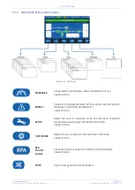
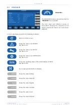
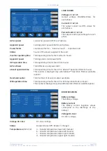
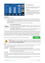
In this mode the keys perform the following functions: 


Shows the main screen 

MEASURES

See 

Section 6.2


Return to HOME screen. 


Shows the main screen 

SETUP

See 

Section 6.4


Shows the main screen 

COMMANDS

See 

Section 6.5


Shows the operating status of the 

RPA PARALLEL SYSTEM

See 

Section 6.6

.


Key to reset general alarm and buzzer.


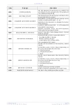
Shows the screen 

User Events


Shows the screen 

Service Events

. Reserved for the 

Service Center


Shows the previous 50 events. 


Shows the previous 5 events. 


Shows the next 5 events. 


Shows the next 50 events. 


Содержание TLE 625 UL S2

Страница 1: ...Supply GE Consumer Industrial SA General Electric Company CH 6595 Riazzino Locarno Switzerland T 41 0 91 850 51 51 F 41 0 91 850 52 52 www gecriticalpower com imagination at work TLES_UL_625 750 1000...

Страница 2: ...evision Concern Date COPYRIGHT 2018 by GE Consumer Industrial SA All rights reserved The information contained in this publication is intended solely for the purposes indicated The present publication...

Страница 3: ...the use of the UPS Thank you for choosing GE START UP AND COMMISSIONING A GE GLOBAL SERVICES FIELD ENGINEER must perform start up and commissioning of the UPS Please Contact GE GLOBAL SERVICES at leas...

Страница 4: ...ned in this document WARNING TLE Series 625 750 1000 is a Category C3 UPS Product according to IEC 62040 2 This is a product for commercial and industrial application in the second environment install...

Страница 5: ...FOR SINGLE TLE SERIES 625 750 1000 57 7 1 1 Initial start up of the TLE Series 625 750 1000 57 7 1 2 Complete UPS shut down 61 7 1 3 Restore to normal operation after System shutdown with Load not sup...

Страница 6: ...ately during Commissioning and Maintenance of the UPS for the following Damaged components squeezed wires and cables or not correctly inserted plugs After removing the sidewalls of the UPS make sure t...

Страница 7: ...to short between individual or separate battery terminals or to the cabinet or rack Do not lay tools or metal parts on top of the battery and do not lay them where they could fall onto the battery or...

Страница 8: ...manual the following symbols are defined WARNING if instruction is not followed injury or serious equipment damage may occur CAUTION internal parts have dangerous voltage present Risk of electric sho...

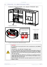
Страница 9: ...1 TLE Series 625 750 General view Fig 2 1 4 Connectivity Rack Fig 2 1 3 Control Panel Fig 2 1 5 Q1 UPS Output switch Fig 2 1 2 TLE Series 625 750 General view with open doors TLES_UL_7500_S1_UPS_GE_02...

Страница 10: ...LE Series 1000 General view Fig 2 2 4 Connectivity Rack Fig 2 2 3 Control Panel Fig 2 2 5 Q1 UPS Output switch Fig 2 2 2 TLE Series 1000 General view with open doors TLES_UL_1000_S1_UPS_GE_02 TLES_160...

Страница 11: ...rt more total Load than any other UPS available allowing you to support a greater number of today s enterprise computing Power Factor Corrected PFC equipment High Efficiency Thanks to type Advanced Ne...

Страница 12: ...iminating all single points of failure The decentralized bypass offers great exibility to up or down grade the system in case future needs might change TLE Series 625 750 1000 BEST IN CLASS EFFICIENCY...

Страница 13: ...anks to modulation strategy applied to IGBT Bridge the rectifier provides clean input power in terms of low THDi and unity power factor Inverter The Inverter converts the DC voltage into a three phase...

Страница 14: ...ble the Load is normally powered through the Automatic Bypass When the Utility Voltage is detected out of the prescribed tolerances the Load is automatically transferred to the Inverter When the Utili...

Страница 15: ...4 3 When a Battery low warning occurs on a unit not necessary to support the present Load this unit will shut down after a timeout period selectable The Load is shared between the other units As the...

Страница 16: ...it condition is corrected the Load will be automatically transferred back to the Inverter Fig 4 2 5 1 Block diagram Automatic Bypass If the UPS is unable to return to normal mode following an automati...

Страница 17: ...common control circuitry see Fig 4 3 1 1 Parallel units for power capacity Several units can be paralleled in order to achieve output power greater than the maximum power of a single unit The maximum...

Страница 18: ...ommunicates with all other modules in order to act or react if necessary adapting to the new conditions 4 3 4 Synchronization All units are identical but one unit is arbitrarily selected as the refere...

Страница 19: ...of UPSs required to maintain a reliable supply to the critical load Then an efficiency optimization algorithm determines the best UPS configuration in order to maintain the running UPS in their highes...

Страница 20: ...hut down To remove the hazardous voltages it is necessary to manually open the IP cabinet fuses FU1 FU2 FU3 Fig 4 3 7 2 checking the presence of any voltage before working on the UPS Read carefully th...

Страница 21: ...be prepared in advance before the installation The installation must be performed only with the UPS system completely shut down The AC Rectifiers input power 4 must be the same with clockwise phase ro...

Страница 22: ...e identification label 4 6 WARRANTY GE operating through its authorized agents warrants that the standard products will be free of defects in materials and workmanship for a period as per contract spe...

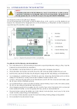
Страница 23: ...G MATERIAL RECYCLING GE in compliance with environment protection uses only environmentally friendly material UPS packing materials must be recycled in compliance with all applicable regulations RECYC...

Страница 24: ...Control Panel positioned on the UPS front door acts as the UPS user interface Main features LCD Touch screen color graphic display See Chapter 6 Multilanguage communication interface English German It...

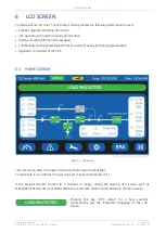
Страница 25: ...can be programmed to meet customer needs by changing parameters Operation commands of the UPS 6 1 HOME SCREEN Fig 6 1 1 LCD screen The LCD screen after 5 minutes of inactivity shuts down the backligh...

Страница 26: ...ction 6 2 EVENTS Shows in chronological order all the events occurred alarms messages commands handling etc See Section 6 3 SETUP Allows the user to customize some UPS functions to specific requiremen...

Страница 27: ...ervice Key yellow color Key for disabling the Service Key procedure Used only by the Service Center LEDS UPS STATUS LED LOAD PROTECTED green color When lit indicates that the UPS is functioning correc...

Страница 28: ...is open LED STOP OPERATION red color It warns about the imminent Inverter stop default parameter 3 min and the consequent Load shut down as result of The battery is fully discharged and the Load cann...

Страница 29: ...Synoptic Diagram LED 1 Rectifier LED 2 Inverter LED 3 Booster Battery charger LED 4 Automatic Bypass LED 5 LOAD Examples of typical scenarios in the Synoptic Diagram Load supplied by Inverter Load sup...

Страница 30: ...rameters like AC DC and various statistics In this mode the keys perform the following functions Return to HOME screen Shows the main screen EVENTS See Section 6 3 Shows the main screen SETUP See Sect...

Страница 31: ...ttery time Total operating time of the UPS on battery in hours BATTERY DISCHARGE COUNTER Residual Charge Level The number of discharges combined with the percentage of the available residual battery c...

Страница 32: ...lity on the last seven days Bypass quality index The statistic evaluation in 100 good 0 bad of the Bypass utility Status Bypass status free blocked INVERTER SCREEN Frequency The output frequency of th...

Страница 33: ...g time for the UPS in hours Active Power Total effective Load power kW eBoost operation time Total operating time for the UPS in eBoost Operation Mode in hours This counter is displayed only when eBoo...

Страница 34: ...e the keys perform the following functions Shows the main screen MEASURES See Section 6 2 Return to HOME screen Shows the main screen SETUP See Section 6 4 Shows the main screen COMMANDS See Section 6...

Страница 35: ...d to an event Nr 511 is the more recent Nr 1 is the first Data MM DD YYYY Exact hour of the moment when the event occurred HH MM SS thousandth Number of standard GE code of the event Explicit text des...

Страница 36: ...JA CRC FAILURE The parallel communication bus system is subject to high errors rate on channel JA 4007 BUS JB CRC FAILURE The parallel communication bus system is subject to high errors rate on channe...

Страница 37: ...VOLTAGE Dangerous high DC Voltage caused Inverter shut down Inverter restarts automatically after Battery returns to floating voltage 4117 BATTERY EARTH FAULT A leakage current to earth has been detec...

Страница 38: ...TRANSFORMER OVERTEMPERATURE The temperature sensor of the Inverter Transformer indicates overtemperature Elapsed stop operation time Inverter shut down With Utility OK Load is transferred on Utility...

Страница 39: ...Load remains supplied by Utility until the alarm stays ON 4522 FAN FAILURE The Fan Control Board indicates a malfunction of one or more ventilators 4530 LOAD LOCKED ON UTILITY Load is locked on Utili...

Страница 40: ...ply Board in particular from the DC supply Can be enabled or disabled with respective parameter 4702 LOSS OF REDUNDANCY A time of lost redundancy superior than specified in respective parameter was de...

Страница 41: ...efined settings 4124 MANUAL AUTOMATIC BOOST CHARGE STOP The automatic boost charge has finished The battery s voltage will return to the maintenance value A manually activated boost charge will finish...

Страница 42: ...d Off on the UPS Control Panel has been pressed with the output circuit switch Q1 closed 4562 DETOUR ON The auxiliary contact indicates that Manual Bypass Q2 only if provided by customer was closed 45...

Страница 43: ...eration Mode will be temporarily inhibited 4609 eBoost INHIBITED LOW LOAD eBoost Operation Mode inhibited due to minimal load not reached 4699 BATTERY TEST IMPOSSIBLE Automatic Battery Test is not pos...

Страница 44: ...ssible without password protection In this mode the keys perform the following functions Shows the main screen MEASURES See Section 6 2 Shows the main screen EVENTS See Section 6 3 Return to HOME scre...

Страница 45: ...d values are XON standing for the XON XOFF protocol or None standing for any protocol PRINTER COMMANDS By using the keys MEASURES ALARMS PARAMETERS ALL it is possible to print selected data NOTE Pleas...

Страница 46: ...the value is No the UPS is normally operating in VFI double conversion mode at all times When the UPS is in eBoost Operating Mode the eBoost LED is ON green light NOTE The configuration of the activat...

Страница 47: ...value NOTE To avoid undesired eBoost Operation Mode verify Date and Time eBoost screen how many hours of eBoost Operation Mode have been selected for each day of the week NOTE The eBoost Operation Mo...

Страница 48: ...test of all Inverters in the system at least 1 minute of normal operation must be programmed during the week the Yes No parameter is automatically disabled if this condition is not satisfied In case t...

Страница 49: ...n how many hours of IEMi Operation Mode have been selected for each day of the week NOTE For IEMi Operation Mode to become active a manual Inverter start is required at start up and after a Load Off r...

Страница 50: ...ows the user to execute UPS operation commands In this mode the keys perform the following functions Shows the main screen MEASURES See Section 6 2 Shows the main screen EVENTS See Section 6 3 Shows t...

Страница 51: ...tching ON command NOTE When eBoost Operation Mode or IEMi Operation Mode is enabled control of Inverter status and selection of the feed path is done autonomously by the UPS control logic Therefore In...

Страница 52: ...status Shows the Module shutdown status ACTIVE NOT ACTIVE System shutdown System shutdown Load Off command for an RPA Parallel System NOTE This command will immediately disconnect the Load System shut...

Страница 53: ...zzer TEST Acoustical alarm test acoustical alarm should be always activated Module shutdown procedure Guides throught the procedures to shutdown a single UPS or a RPA Parallel System unit Attention Fo...

Страница 54: ...some information on the RPA Parallel System In this mode the keys perform the following functions Shows the main screen MEASURES See Section 6 2 NOTE During IEMi Operation Mode the Percent Load inform...

Страница 55: ...t of the RPA System Parallel Input Utility status for RECT Rectifier and BYP Bypass Battery status for CHRG Battery Charger green color On grey color Off Q1 Load output switch Q2 Manual Bypass switch...

Страница 56: ...step instructions given below However we recommend that at least the initial procedure should be performed by an instructed person Check after every step for correct reaction of the UPS LEDs on the pa...

Страница 57: ...afety screens are fixed in their position The switch Q1 is open Pos O and the External Battery Protections must be open Pos O Q1 UPS Output switch LEDs on Synoptic Diagram LED 1 Rectifier LED 2 Invert...

Страница 58: ...grity and reliability of the UPS UPS Language This parameter allows the choice of language used to display the information Date dd mm yyyy You can adjust the date of the real time clock existing in th...

Страница 59: ...harge 1 41Vdc for cell 284 309 cells x 1 41Vdc 401 436Vdc NiCd Battery with boost charge 1 41 1 55 boost charge Vdc for cell 281 cells x 1 41Vdc 397 436 Vdc Flooded Lead Acid Battery without boost cha...

Страница 60: ...ions NOTE Before performing the next procedure 4 make sure that the LED 3 Booster Battery charger is lit 4 Insert the Inverter performing the command Inverter ON Perform the Inverter ON command from t...

Страница 61: ...hutdown Load is disconnected from UPS Rectifier and Inverter are shut down and all contactors are opened LED 1 Rectifier and LED 2 Inverter are OFF LED ALARM is lit 2 Open Q1 UPS Output switch Pos O 3...

Страница 62: ...MUST BE CLOSED External Battery Protections MUST BE DISCONNECTED If eBoost option is available make sure that eBoost Operation Mode is disabled before starting this procedure View of the Synoptic Dia...

Страница 63: ...ctions NOTE Before performing the next procedure 3 make sure that the LED 3 Booster Battery charger is lit 3 Insert the Inverter performing the command Inverter ON Perform the Inverter ON command from...

Страница 64: ...s MUST BE DISCONNECTED If eBoost option is available make sure that eBoost Operation Mode is disabled before starting this procedure View of the Synoptic Diagram after performed the command EPO Emerge...

Страница 65: ...ctions NOTE Before performing the next procedure 4 make sure that the LED 3 Booster Battery charger is lit 4 Insert the Inverter performing the command Inverter ON Perform the Inverter ON command from...

Страница 66: ...open Open the front door and make sure that All the connections to the input output terminals or bus bars of the UPS have been made correctly The safety screens are fixed in their position The switch...

Страница 67: ...grity and reliability of the UPS UPS Language This parameter allows the choice of language used to display the information Date dd mm yyyy You can adjust the date of the real time clock existing in th...

Страница 68: ...harge 1 41Vdc for cell 284 309 cells x 1 41Vdc 401 436Vdc NiCd Battery with boost charge 1 41 1 55 boost charge Vdc for cell 281 cells x 1 41Vdc 397 436 Vdc Flooded Lead Acid Battery without boost cha...

Страница 69: ...ht DC polarities on both side of the switch fuse holder 3 Connect the Battery to the UPS by closing the External Battery Protections 4 Insert the Inverter performing the command Inverter ON Before per...

Страница 70: ...rom UPS Rectifier and Inverter are shut down and all contactors are opened LED 1 Rectifier and LED 2 Inverter are OFF LED ALARM is lit 2 Open Q1 UPS Output switch Pos O 3 Disconnect the Battery from t...

Страница 71: ...tatus Q1 UPS Output switch MUST BE CLOSED External Battery Protections MUST BE DISCONNECTED View of the Synoptic Diagram after performed the command System shutdown with LOAD NOT SUPPLIED 1 Restore th...

Страница 72: ...ng the command Inverter ON Perform the Inverter ON command from the screen Commands 1 Inverter ON Soft start of Inverter indicated with blinking LED 2 Inverter At the end of Soft start the LED 2 Inver...

Страница 73: ...ration make sure that the UPS is in the following status Q1 UPS Output switch MUST BE CLOSED External Battery Protections MUST BE DISCONNECTED View of the Synoptic Diagram after performed the command...

Страница 74: ...y closing the External Battery Protections NOTE Before performing the next procedure 4 make sure that the LED 3 Booster Battery charger is lit 4 Insert the Inverter performing the command Inverter ON...

Страница 75: ...e fixed in their position The switch Q1 is open Pos O and the External Battery Protections must be open Pos O Q1 UPS Output switch LEDs on Synoptic Diagram LED 1 Rectifier LED 2 Inverter LED 3 Booster...

Страница 76: ...grity and reliability of the UPS UPS Language This parameter allows the choice of language used to display the information Date dd mm yyyy You can adjust the date of the real time clock existing in th...

Страница 77: ...harge 1 41Vdc for cell 284 309 cells x 1 41Vdc 401 436Vdc NiCd Battery with boost charge 1 41 1 55 boost charge Vdc for cell 281 cells x 1 41Vdc 397 436 Vdc Flooded Lead Acid Battery without boost cha...

Страница 78: ...ure It indicates that the DC link 1 and DC link 2 has reached 400Vdc see screen MEASURES Rectifier Attention check the right DC polarities on both side of the switch fuse holder 3 Connect the Battery...

Страница 79: ...to Inverter LED ALARM turns Off and the LED LOAD PROTECTED must be lit The Synoptic Diagram on all UPS units must display the status LOAD SUPPLIED BY INVERTER Synoptic Diagram of first unit Synoptic D...

Страница 80: ...tatus Load supplied from all Inverters of the Redundant Parallel System 1 Disconnect the Inverter performing the Inverter OFF command on the Unit to separate 1 Perform the Inverter OFF command from th...

Страница 81: ...Protections Press MUTE key to reset Acoustical Alarm LED ALARM remains lit Synoptic diagram of the unit to separate Synoptic diagram of other units NOTE Before performing the next procedure 5 wait 5...

Страница 82: ...before starting this procedure Open the front door of the Unit to reconnect and make sure that All the connections to the input output terminals or bus bars of the UPS have been made correctly The pro...

Страница 83: ...o reconnect by closing the External Battery Protections Synoptic diagram of the unit to reconnect Synoptic diagram of other units 4 Insert the Inverter performing the command Inverter ON on the Unit t...

Страница 84: ...screen Commands 1 System shutdown Shutdown Load is disconnected from UPS Parallel System Rectifiers and Inverters are shut down and all Contactors are opened LED ALARM is lit Synoptic diagram of first...

Страница 85: ...is disabled before starting this procedure If IEMi option is available make sure that IEMi Operation Mode is disabled before starting this procedure View of the Synoptic Diagram on all UPS units afte...

Страница 86: ...rter remains lit In case of sufficient output power the output will transfer to Inverter LED ALARM turns Off and the LED LOAD PROTECTED must be lit Synoptic diagram of first unit Synoptic diagram of o...

Страница 87: ...efore starting this procedure If IEMi option is available make sure that IEMi Operation Mode is disabled before starting this procedure View of the Synoptic Diagram on all UPS units after performed th...

Страница 88: ...rter remains lit In case of sufficient output power the output will transfer to Inverter LED ALARM turns Off and the LED LOAD PROTECTED must be lit Synoptic diagram of first unit Synoptic diagram of o...

Страница 89: ...itical conditions In addition comprehensive data collection and analysis improves diagnostics capability and enhances response time Continuous monitoring and ongoing maintenance help ensure maximum pe...

Страница 90: ...tion the unit has not been serviced for the last 20 000 hours by a GE TRAINED TECHNICIAN Some components of the UPS which need periodic maintenance if not replaced could cause a reliability reduction...

Страница 91: ...Battery Test to verify the full runtime of the Battery the charger needs at least 8 hours to recharge the Battery up to 90 of its capacity Long shut down periods of the UPS system To guarantee that t...

Страница 92: ...10 docx User Manual TLE Series 625 750 1000 UL S2 10 NOTES 10 1 NOTES FORM It is recommended to note in this section Notes with date and short description all the operations performed on the UPS as ma...

Отзывы: