GE Healthcare
Senographe DS
Revision 1
Service Information and Procedures Class A 2385072-16-8EN
Job Card CHK A003 - UPS Batteries
Page no. 1737
Chapter 9
JC-CHK-A-003.fm
Job Card CHK A003 - UPS Batteries
Chapter 9
1
SUPPLIES
None
2
TOOLS
None
3
REQUIRED EFFORT
Personnel: 1 Field Engineer
Time: 5 minutes for UPS function check and 60 minutes for battery recalibration
4
SAFETY PRECAUTIONS
.None
5
PREREQUISITES
None
6
UPS FUNCTION CHECK
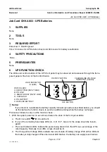
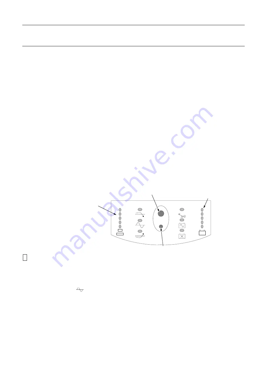
The LEDs and control buttons of the UPS front panel may be observed and accessed through the trans-
parent panel at the front of the Control Station.
! Notice:
If you intend to re-calibrate the battery capacity indicator (procedure described below), you should
do this before the function check, to avoid an additional delay while the battery recharges.
Proceed as follows to carry out the function check:
1. With the system powered on as normal, observe the state of the front panel LEDs:
a. The On Line LED
(B) should be lit.
b. If any of the remaining five status LEDs (A, C, D, E, F, G) are lit, the cause should be investi-
gated.
c. The Load Indicator LEDs indicate the power being drawn from the UPS as a percentage of the
rated capacity. Normally, four LEDs or less should be lit.
d. The Charge/Line Voltage LEDs indicate the current state of battery charge. With all five LEDs lit,
the battery is fully charged. When the lowest LED flashes, the battery can supply less than two
A
B
C
D
E
F
ON/TEST BUTTON
LOAD INDICATOR
OFF BUTTON
CHARGE/LINE VOLTAGE
INDICATOR (5 LEDS)
A - SMART TRIM (INPUT HIGH)
B - ON LINE
D - OVERLOAD
E - ON BATTERY
F - REPLACE BATTERY
STATUS LEDS:
C - SMART BOOST (INPUT LOW)
(5 LEDS)

