


Manual title
Table of Contents
11-0768DAV-B/ December 2003
19
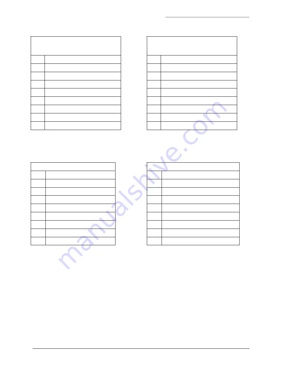
Table 11. J2/J3 Connections for RS485 2-Wire Data
SW1 / SW2 – Position 6 (standard offset)
Position 7 (1V offset)
Position 8 (2V offset)
Pin Signal
1 GROUND/SHIELD
2 NO
CONNECTION
3 NO
CONNECTION
4
+5 VDC BIAS OUT
5 RS485
-
6 RS485
+
7
TERMINATION – TIE TO PIN 5
8 GROUND
Table 12. J2/J3 Connections for RS485 4-Wire Data
SW1 / SW2 – Position 9 (standard offset)
Position A (1V offset)
Position B (2V offset)
Pin Signal
1 GROUND/SHIELD
2
RS485 OUT -
3 RS485
OUT
+
4
+5 VDC BIAS OUT
5
RS485 IN -
6
RS485 IN +
7
TERMINATION – TIE TO PIN 5
8 GROUND
Table 13. J2/J3 Connections for SensorNet Data
SW1 / SW2 – Position 6
Pin Signal
1 GROUND/SHIELD
2 NO
CONNECTION
3 NO
CONNECTION
4
+5 VDC BIAS OUT
5 SENSORNET
-
6 SENSORNET
+
7
TERMINATION – TIE TO PIN 5
8 GROUND
Table 14. J2/J3 Connections for Test Mode Loopback
SW1 / SW2 – Position F
Pin Signal
1 NO
CONNECTION
2
TIE TO PIN 5
3
TIE TO PIN 6
4 NO
CONNECTION
5
TIE TO PIN 2
6
TIE TO PIN 3
7 NO
CONNECTION
8 GROUND
3.3.3
B
UILT
-I
N
T
ERMINATION
The S768DAV features a built-in termination on the Interface Board for RS485, Manchester, Biphase, and
SensorNet installations. Refer to Table 4, and Table 10 through Table 13.


