RPV311
Chapter 12
– RPV Tools
RPV311-TM-EN-7
181
1.5.2
Interface
When installing the RPV Tools, it creates a desktop icon for quick access. The
configuration interface can be accessed directly via this icon.
To access the configuration interface, do the following:
1.
Click Start
>
Programs
>
Accessories
>
Command Prompt;
2.
At Prompt, access C:\RPV\goosemon
_
config\resources;
3.
Run the Goosemon
_
Config.exe file and the application will open.
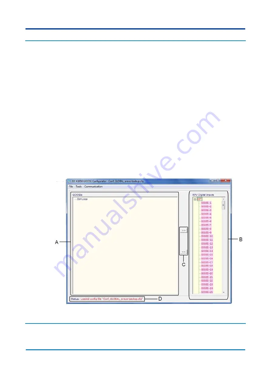
The initial screen of the GOOSE Configurator application is shown in
has the following characteristics:
A
The GOOSE's list the configuration files loaded. These files are divided into GOOSE
C
ONTROL
B
LOCK
, which are composed of datasets with binary elements that can be
associated with the digital channels of the RPV.
B
The Digital channel of the RPV has the 320 binary magnitudes of the RPV, which
can be associated to GOOSE messages. These inputs shall be identified in the RPV.
C
The buttons allow association or disassociation of a GOOSE
C
ONTROL
B
LOCK
to a
digital input of the RPV.
D
The S
TATUS
indicates the status of each operation.
Figure 81: Initial screen of the GOOSE Configurator
1.5.3
Configuration
Содержание RPV311
Страница 2: ......
Страница 44: ......
Страница 99: ...RPV311 Chapter 5 Operation RPV311 TM EN 7 99 Figure 46 Status monitoring sequence ...
Страница 101: ...RPV311 Chapter 5 Operation RPV311 TM EN 7 101 Figure 47 Monitoring sequence ...
Страница 104: ...Chapter 5 Operation RPV311 104 RPV311 TM EN 7 Figure 49 Records monitoring sequence harmonics flicker and SOE ...
Страница 106: ...Chapter 5 Operation RPV311 106 RPV311 TM EN 7 Figure 50 Equipment settings monitoring sequence ...
Страница 107: ...RPV311 Chapter 5 Operation RPV311 TM EN 7 107 Figure 51 Circuit and channel settings monitoring sequence ...
Страница 108: ...Chapter 5 Operation RPV311 108 RPV311 TM EN 7 Figure 52 Relays PMU and MODBUS settings monitoring sequence ...
Страница 110: ...Chapter 5 Operation RPV311 110 RPV311 TM EN 7 Figure 53 General information monitoring sequence ...
Страница 142: ......
Страница 149: ...RPV311 Chapter 9 TW Fault Locator RPV311 TM EN 7 149 Figure 75 TW Fault Location example 1 ...
Страница 152: ......
Страница 160: ......
Страница 162: ......
Страница 164: ......
Страница 204: ......
Страница 265: ...Chapter 17 Technical Specifications RPV311 RPV311 TM EN 7 265 Figure 142 RPV311 Dimensions ...
Страница 275: ...Chapter 17 Technical Specifications RPV311 RPV311 TM EN 7 275 Figure 143 RA331 RA332 and RA333 dimensions ...
Страница 279: ...RPV311 Appendix A Equipment Log RPV311 TM EN 7 279 ...


