


1BChapter 2: Installation
8
TruVision Mini PTZ 12X Camera User Manual
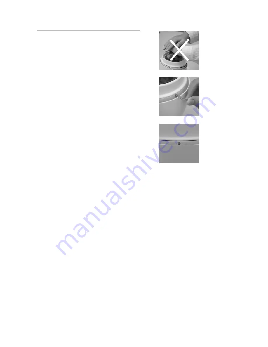
Caution:
DO NOT press on the top of the bubble
as shown in the figure as it might damage the
unit.
6. Screw the bubble and dome camera body
together with the supplied M3
standard/security screw. Use the supplied
security torx to fasten the security screws.
7. Further secure the bubble by turning the two
slotted screws counterclockwise so that they
touch the dome camera housing.
8. Set the DIP switches.
Dome camera DIP switches
Configure the dome camera’s ID and communication protocol before connecting the
analog dome camera to other devices. The DIP switches used for configuring these
settings are located on the top of the dome camera housing. See Figure 3 on page 9
for the location of the DIP switches on both the indoor and outdoor dome cameras.
The 22-pin connector for I/O interface cable connection is located on the back plate.
Содержание PTZ 12X
Страница 1: ...GE Security P N 1069515_EN REV A ISS 26NOV09 TruVision Mini PTZ 12X Camera User Manual ...
Страница 52: ... Advanced setup 48 TruVision Mini PTZ 12X Camera User Manual ...
Страница 60: ...6BAppendix B Camera settings checklist 56 TruVision Mini PTZ 12X Camera User Manual ...
Страница 65: ......