background image

17

Installation Instructions

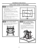
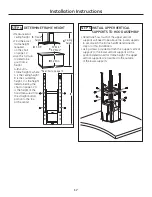
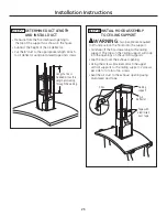
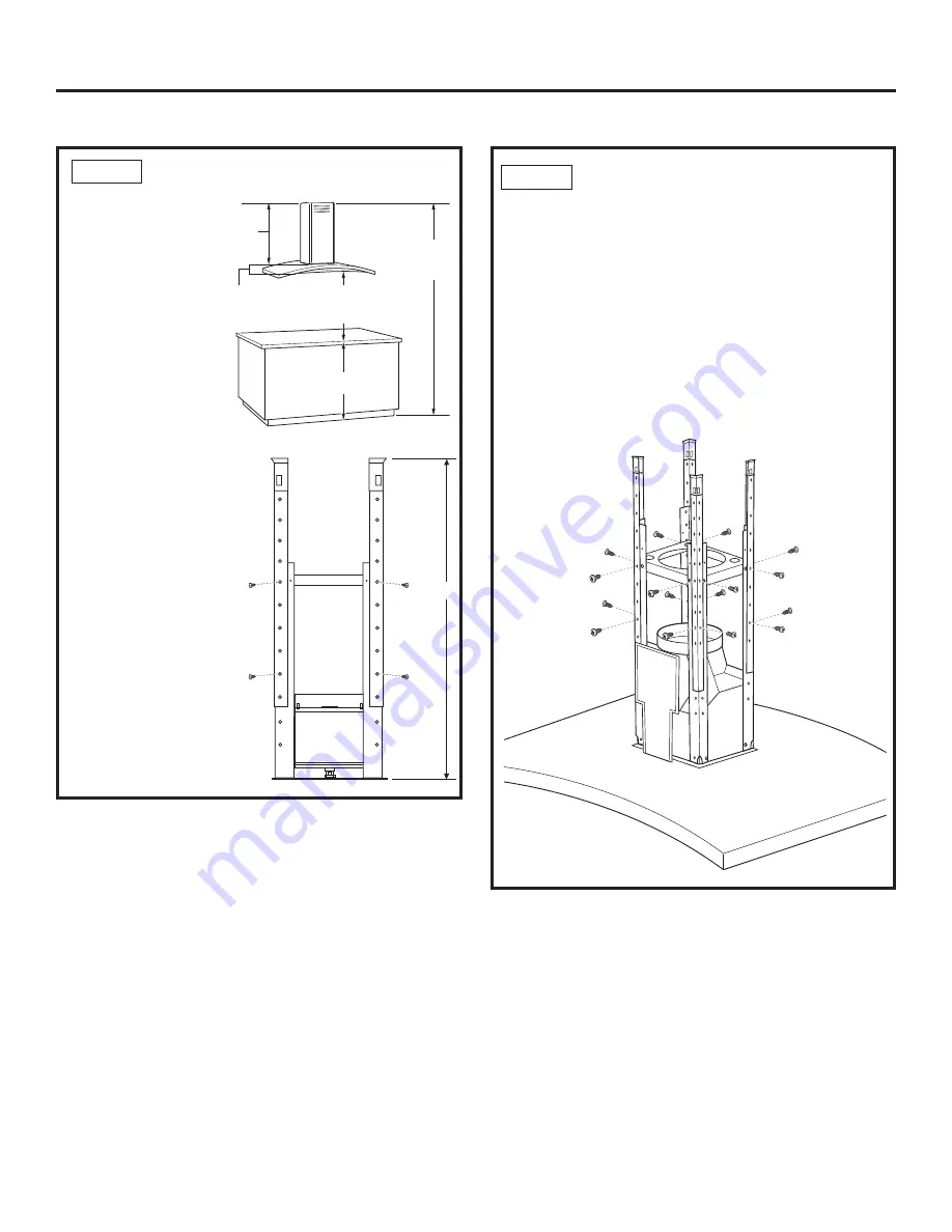
STEP 5  INSTALL UPPER VERTICAL

SUPPORTS TO HOOD ASSEMBLY

• Determine how much of the upper vertical

supports will need to be above the lower supports
to accomplish the frame height determined in
step 4 for this installation.

• Using screws provided, attach the 4 upper vertical

supports to the lower vertical supports at the
position determined for frame height. The upper
vertical supports are mounted to the outside 
of the lower supports.

STEP 4  DETERMINE FRAME HEIGHT

•Measure exact

ceiling height.

•Find the exact

frame height
required 
on the chart 
on page 12.

•Use this formula

to determine
your frame
height:
A-(B+C+D) =
Frame height E where
A is the ceiling height,
B is the countertop
height, C is the height
determined by the
chart on page 12, D 
is the height of the
hood measured from
the straight bottom
portion to the top 
at the center.

24" Min.*

30" Max.*

36" Min.

Frame

height

2-3/8"

Ceiling

height

E

E

A

B

D

C

*See Chart on page 12.

Содержание Profile PV977

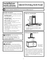
Страница 1: ...es 6 Installation Instructions Installation Preparation 7 15 Vented to the Outside 16 20 Recirculating 21 26 Troubleshooting Tips 27 28 Consumer Support Consumer Support 30 Warranty 29 PV977 Owner s Manual and Installation Instructions ge com Write the model and serial numbers here Model __________________________ Serial __________________________ You can find them on a label on the inside of the ...

Страница 2: ...nd to properly exhaust air be sure to duct air outside Do not vent exhaust air into spaces within walls or ceilings or into attics crawl spaces or garages WARNING TO REDUCE THE RISK OF INJURY TO PERSONS IN THE EVENT OF A RANGE TOP GREASE FIRE OBSERVE THE FOLLOWING A SMOTHERFLAMES with a close fitting lid cookie sheet or metal tray then turn off the burner BE CAREFUL TO PREVENT BURNS If the flames ...

Страница 3: ...O PERSONS OBSERVE THE FOLLOWING A Installation work and electrical wiring must be done by qualified person s in accordance with all applicable codes and standards including fire rated construction B Sufficient air is needed for proper combustion and exhausting of gases through the flue chimney of fuel burning equipment to prevent back drafting Follow the heating equipment manufacturer s guidelines...

Страница 4: ...d setting There are 4 fan levels LOW MED HIGH BOOST and OFF If you continue to press the or buttons the fan will cycle back through the settings NOTE There is an audible beep each time a button is pressed This is normal NOTE The collars around the buttons will illuminate when pressed This is normal The collars will automatically turn off if the hood is turned off HEAT SENSOR This hood is equipped ...

Страница 5: ...ll occur in the dishwasher Charcoal Filter For recirculating installation only If the model is not vented to the outside the air will be recirculated through a disposable charcoal filter that helps remove smoke and odors The charcoal filter should be replaced when it is noticeably dirty or discolored usually after 6 to 12 months depending on hood usage NOTE DO NOT rinse or put charcoal filter in a...

Страница 6: ...t bulbs 1 Remove the lamp lens cover by inserting a small flat blade screwdriver into each of the three slots and gently prying it free NOTE Do not remove the outer trim ring lamp assembly 2 Wear gloves Do not touch the bulb with your bare fingers Skin oils can cause early lamp failure 3 Grasp the bulb and pull it straight out 4 Replace with the same wattage Early bulb failure and damage to or fai...

Страница 7: ...roduct failure due to improper installation is not covered under the Warranty FOR YOUR SAFETY WARNING Before beginning the installation switch power off at service panel and lock the service disconnecting means to prevent power from being switched on accidentally When the service disconnecting means cannot be locked securely fasten a prominent warning device such as a tag to the service panel CAUT...

Страница 8: ...installation refer to table on page 12 POWER SUPPLY IMPORTANT Please read carefully WARNING FOR PERSONAL SAFETY THIS APPLIANCE MUST BE PROPERLY GROUNDED Remove house fuse or open circuit breaker before beginning installation Do not use an extension cord or adapter plug with this appliance Follow National Electrical Codes or prevailing local codes and ordinances Electrical Supply This vent hood mus...

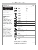
Страница 9: ...lly vented systems follow the heating equipment manufacturer s guidelines and safety standards such as those published by NFPA and ASHRAE Total Equivalent Quantity Equivalent Duct Piece Dimensions Length Used Length Round 1 ft straight per foot length 3 1 4 x 12 1 ft straight per foot length 90 elbow 17 ft 45 elbow 10 ft 3 1 4 x 12 90 elbow 43 ft 3 1 4 x 12 45 elbow 26 ft 3 1 4 x 12 90 flat elbow ...

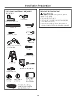
Страница 10: ...ladder Saber saw or Key Hole saw Phillips screwdriver Strain relief for junction box 8 Round metal duct length to suit installation Hammer Electric drill with 3 16 bits 2 Phillips head Flashlight UL listed wire nuts REMOVE THE PACKAGING CAUTION Wear gloves to protect against sharp edges Remove the duct covers Remove the hardware bag literature package and other boxed parts Remove and properly disc...

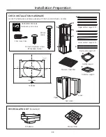
Страница 11: ...eded Cut one 1 2 Dia Wire Access Hole as Needed Drill 3 16 Pilot Holes Approx 1 1 2 Deep 4 Places 8 1 4 To Centerline of Pilot Holes 10 5 16 To Centerline of Pilot Holes 10 5 16 To Centerline of Pilot Holes 31 14772 Printed in Mexico 12 08 JR 4 Wood screws 73 Hood attachment screws 70 required 3 extra Duct covers Charcoal filter C Ceiling support Horizontal support Upper vertical supports 4 Lower ...

Страница 12: ...n ceiling height PV977 Island Upper Duct Cover 29 92 Lower Duct Cover 25 98 Counter to Hood Height Actual Possible Ceiling Possible VENTED RECIRCULATING Height Installation Height Installation Height 7 11 24 24 8 0 24 to 25 24 to 25 8 1 24 to 26 24 to 26 8 2 24 to 27 24 to 27 8 3 24 to 28 24 to 28 8 4 24 to 29 24 to 29 8 5 24 to 30 24 to 30 8 6 24 to 30 24 to 30 8 7 24 to 30 24 to 30 8 8 24 to 30 ...

Страница 13: ...8 1 4 8 Duct Front of hood 2x4 Cross framing wood supports Cooktop outline Align duct to center of cooktop Ceiling Support Structure At the hood location install cross framing between ceiling joists as shown 2x4 wood supports are required to support the weight of the hood Arrange cross framing in the ceiling to suit the existing structure Your ceiling joists will be like one of the following examp...

Страница 14: ...1 4 8 Duct Front of hood 2x4 Cross framing wood supports Cooktop outline Align duct to center of cooktop 16 Joist spacing 8 Duct Cooktop outline Align duct to center of cooktop EXAMPLE B EXAMPLE C Front ofhood 10 5 16 Install cross framing symmetrically over duct cooktop centerline 2x4 Cross framing wood supports Install cross framing symmetrically over duct cooktop centerline 8 1 4 10 5 16 ...

Страница 15: ...Be sure to mark location of the ceiling joists and cross framing Check to be sure the ceiling is level use shims if necessary Secure each 2 x 4 block with at least four 4 10 wood screws 3 long not supplied Use 8 wood screws total for the two supports The cross framing must be accurately aligned to assure correct positioning of the hood The cross framing must be level in all directions Check with a...

Страница 16: ...s provided attach the ceiling support to the ceiling over duct opening hole using pilot holes drilled in step 1 STEP 3 INSTALL LOWER VERTICAL AND HORIZONTAL SUPPORTS TO HOOD ASSEMBLY Using screws provided attach the 4 lower vertical supports to the hood assembly with 4 screws per support Using screws provided install the horizontal support in the top outer holes of the vertical supports 36 HOOD TE...

Страница 17: ... frame height The upper vertical supports are mounted to the outside of the lower supports STEP 4 DETERMINE FRAME HEIGHT Measure exact ceiling height Find the exact frame height required on the chart on page 12 Use this formula to determine your frame height A B C D Frame height E where A is the ceiling height B is the countertop height C is the height determined by the chart on page 12 D is the h...

Страница 18: ...ING SUPPORT WARNING Two people are required to lift and position the hood onto the support Lift the hood assembly up to the ceiling support Carefully fit the newly assembled duct over exhaust opening on the hood assembly The clips on the ceiling support will snap into the large openings on the upper vertical supports Using the screws provided attach the upper vertical supports to the ceiling suppo...

Страница 19: ...Remove the 6 screws on the junction box cover and the knockout on the top left side Secure the house wiring to the junction box with a strain relief not provided Connect the white lead to the branch circuit white lead Connect the black lead to the branch circuit black lead Connect the green yellow lead to the branch circuit green lead or bare ground lead Secure all the connections with wire nuts o...

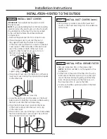
Страница 20: ...e venting slots at the top If the hood is vented to the outside the holes should be positioned on the bottom Remove the protective film from all duct covers Place one upper duct cover over the rear of the support assembly The tabs on the edges of the duct cover will slide into a notch on the duct cover support When all 6 tabs on the duct cover are in the notches on both of the duct cover supports ...

Страница 21: ...ss Hole as Needed Drill 3 16 Pilot Holes Approx 1 1 2 Deep 4 Places 8 1 4 To Centerline of Pilot Holes 10 5 16 To Centerline of Pilot Holes 10 5 16 To Centerline of Pilot Holes 31 14772 Printed in Mexico 12 08 JR STEP 3 INSTALL CEILING SUPPORT AND DEFLECTOR ASSEMBLY Using the 4 wood screws provided attach the ceiling support using the pilot holes drilled in step 1 Screws STEP 2 INSTALL AIR DEFLECT...

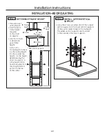
Страница 22: ...e 12 D is the height of the hood measured from the straight bottom portion to the top at the center 24 Min 30 Max 36 Min Frame height 2 3 8 Ceiling height 22 Installation Instructions INSTALLATION RECIRCULATING E A B D C STEP 6 INSTALL UPPER VERTICAL SUPPORT Using the screws provided attach the 4 upper vertical supports to the lower vertical supports at the position determined for frame height The...

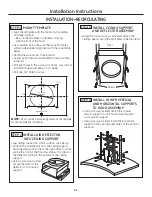
Страница 23: ...g STEP 8 INSTALL HOOD ASSEMBLY TO CEILING SUPPORT WARNING Two people are required to lift and position the hood onto the support Carefully lift the hood assembly to the ceiling support The clips on the ceiling support will snap into the openings on the vertical supports Slip the duct over the exhaust opening Using the screws provided attach the upper vertical supports to the ceiling support 2 scre...

Страница 24: ...n relief not provided Connect the white lead to the branch circuit white lead Connect the black lead to the branch circuit black lead Connect the green yellow lead to the branch circuit green lead or bare ground lead Secure all the connections with wire nuts on each electrical connector Push the wires into the junction box and replace the cover Be sure the wires are not pinched Secure the junction...

Страница 25: ...n the duct cover are in the notches on both of the duct cover supports slide the duct cover up so it sits on the duct cover support spring clip Left duct cover Duct cover support spring clip STEP 11 INSTALL DUCT COVERS cont Place a duct cover clip onto the bottom of the rear lower duct cover locking the clip into place Repeat on the other side Lower the duct cover into the recess on the hood Place...

Страница 26: ...age the flange Metal Grease Filter Remove the protective film on the grease filter Fit the tabs at the end of the filter into the slots in left side of the filter opening Lift up the right side of the filter and push gently until the filter locks into place Make sure the filter lock is in the closed position to secure the filter To remove the filter pull downward on the filter lock to release ...

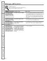
Страница 27: ...er venting GE service technicians cannot correct this issue if installed improperly Fan fails to circulate air Obstructions in duct work Make sure nothing is blocking the vent Make sure or moves air slower your wall or roof cap has a blade or door than normal and or fan Damper blade on wall or roof Make sure damper swings freely Damper blades may is making loud or cap may not be open flip over and...

Страница 28: ... original setting once the heat sensor detects the temperature has reached a safe condition A collar around a push Push button may be stuck Check affected push button and ensure that it is not button is not illuminating stuck Call for service if problem persists when pressed Two or more collars Two or more push buttons Check affected push buttons and ensure that they around the push buttons may be...

Страница 29: ...harge or you may be required to bring the product to an Authorized GE Service Location for service In Alaska the warranty excludes the cost of shipping or service calls to your home Some states do not allow the exclusion or limitation of incidental or consequential damages This warranty gives you specific legal rights and you may also have other rights which vary from state to state To know what y...

Страница 30: ...r details of GE s Universal Design applications including kitchen design ideas for people with disabilities check out our Website today For the hearing impaired please call 800 TDD GEAC 800 833 4322 Extended Warranties ge com Purchase a GEextended warranty and learn about special discounts that are available while your warranty is still in effect You can purchase it on line anytime or call 800 626...

Страница 31: ...Instrucciones de instalación Preparación para la instalación 7 15 Ventilación hacia el exterior 16 20 Recirculación 21 26 Consejos para la identificación y solución de problemas 27 28 Apoyo al cliente Apoyo al cliente 30 Garantía 29 PV977 Manual del Propietario e Instrucciones de Instalación ge com Escriba los números de modelo y de serie aquí Modelo ________________ Serie __________________ Usted...

Страница 32: ...escape correctamente asegúrese de dirigir el aire del conducto hacia el exterior No ventile el aire de escape en espacios dentro de paredes o cielorrasos o en áticos huecos sanitarios o garajes ADVERTENCIA PARA REDUCIR EL RIESGO DE LESIONES A PERSONAS SI SE PRODUCE UN INCENDIO DE GRASA EN LA ESTUFA CUMPLA CON LOS SIGUIENTES PUNTOS A APAGUE LAS LLAMAS con una tapa que ajuste bien una plancha para g...

Страница 33: ...do eléctrico deben realizarlo personas calificadas en cumplimiento con todos los códigos y normas aplicables incluyendo construcción con clasificación para incendios B Se necesita suficiente aire para una combustión y escape de gases adecuados a través de la ventilación chimenea de equipamiento de combustión de combustible para evitar la contracorriente Siga las pautas y normas de seguridad de fab...

Страница 34: ...ontinúa presionando los botones o el ventilador se desplazará a través de las configuraciones NOTA Puede oírse un pitido cada vez que se presiona un botón Esto es normal NOTA Los collarines ubicados alrededor de los botones se iluminan cuando se presionan los botones Esto es normal Los collarines se apagan en forma automática cuando se apaga la campana SENSOR DE CALOR Esta campana cuenta con un se...

Страница 35: ...tro de grasa metálico 2 Quite el filtro de carbón presionando sobre las dos manijas de las lengüetas de bloqueo Para volver a colocar 1 Introduzca el filtro de carbón dentro de la abertura Presione las manijas de las lengüetas de bloqueo hacia el centro y libérelas para sujetar las lengüetas de bloqueo 2 Vuelva a colocar el filtro metálico ver la sección Filtro de grasa metálico Filtro de grasa me...

Страница 36: ...do NOTA No quite el anillo exterior montaje de la bombilla 2 Utilice guantes No toque la bombilla con las manos desnudas Los aceites de la piel pueden provocar una falla temprana de la bombilla 3 Tome la bombilla y quítele directamente hacia afuera 4 Coloque una bombilla de repuesto del mismo vataje Si el vataje es muy elevado pueden producirse daños prematuros de la bombilla o daños o fallas en e...

Страница 37: ...nes para referencia futura Nivel de capacidad La instalación de esta campana de ventilación requiere capacidades mecánicas y eléctricas básicas Tiempo de finalización Aproximadamente de 4 a 6 horas El instalador tiene la responsabilidad de efectuar una instalación adecuada La Garantía no cubre las fallas del producto debido a una instalación incorrecta PARA SU SEGURIDAD ADVERTENCIA Antes de comenz...

Страница 38: ...cto provistas para instalación ventilada e instalación con recirculación consulte la tabla de la página 12 8 PREPARACIÓN PARA INSTALAR LA CAMPANA SUMINISTRO DE ENERGÍA IMPORTANTE Tenga a bien leer cuidadosamente ADVERTENCIA PARA SEGURIDAD PERSONAL ESTE APARATO DEBE CONECTARSE A TIERRA DE MANERA ADECUADA Quite el fusible o abra el interruptor de circuitos antes de comenzar la instalación No utilice...

Страница 39: ...lación natural siga las pautas y normas de seguridad del fabricante del equipamiento de calefacción tales como las publicadas por NFPA y ASHRAE Longitud Pieza Longitud Cantidad equivalente de conducto Dimensiones equivalente utilizada total Redondo y recto 1 pie recto por longitud de pie Recto de 1 pie recto 3 1 4 x 12 por longitud de pie Codo de 90 17 pies Codo de 45 10 pies Codo de 90 de 3 1 4 x...

Страница 40: ...DOS NO SUMINISTRADOS Lápiz y cinta métrica Alicates Alicate pelacables Tijeras para metal Nivel de burbuja de aire Cinta aislante de aluminio Gafas de seguridad Cable de 120V 60Hz 15 o 20 amperios de 2 hilos con circuito derivado con conexión a tierra Escalera Sierra sable o serrucho de calar Destornillador de estrella Alivio de tensión para la caja de conexiones Conducto de metal redondo de 8 lon...

Страница 41: ...sea necesario Perfore orificios piloto de 3 16 de aprox 1 1 2 de profundidad en los 4 lugares indicados 8 1 4 hacia la línea central de los orificios piloto 10 5 16 hacia la línea central de los orificios piloto 10 5 16 hacia la línea central de los orificios piloto 31 14772 Impreso en México 12 08 JR PLANTILLA PARA CAMPANA DE 36 4 tornillos para madera 73 tornillos de sujeción de la campana 70 re...

Страница 42: ...Min 30 Max 36 Min La altura de instalación exacta depende de la altura del cielorraso PV977 Isla Cubierta de conducto superior 29 92 Cubierta de conducto inferior 25 98 Mostrador hasta la altura de la campana Altura Altura de instalación Altura de instalación real del posible CON posible CON cielorraso VENTILACIÓN RECIRCULACIÓN 7 11 24 24 8 0 24 a 25 24 a 25 8 1 24 a 26 24 a 26 8 2 24 a 27 24 a 27...

Страница 43: ...ortes de madera del armazón cruzado de 2 x 4 Contorno de la estufa Alinee el conducto con el centro de la estufa Estructura del soporte de cielorraso En la ubicación de la campana instale un armazón cruzado entre las vigas como se indica Se requieren soportes de madera de 2 x 4 para sostener el peso de la campana Coloque el armazón cruzado en el cielorraso de modo que se ajuste a la estructura exi...

Страница 44: ... armazón cruzado de 2 x 4 Contorno de la estufa Alinee el conducto con el centro de la estufa Espacio para viga de 16 Conducto de 8 Contorno de la estufa Alinee el conducto con el centro de la estufa EJEMPLO B EJEMPLO C 10 5 16 Instale el armazón cruzado en forma simétrica sobre la línea central del conducto estufa Soportes de madera del armazón cruzado de 2 x 4 Instale el armazón cruzado en forma...

Страница 45: ...ielorraso Asegúrese de marcar la ubicación de las vigas del cielorraso y del armazón cruzado Controle que el cielorraso esté nivelado utilice cuñas si fuese necesario Fije cada bloque de 2 x 4 con por lo menos cuatro 4 tornillos para madera N 10 de 3 de longitud no provistos Utilice un total de 8 tornillos para madera para los dos soportes El armazón cruzado debe estar precisamente alineado para g...

Страница 46: ...abertura del conducto mediante los orificios piloto perforados en el paso 1 PASO 3 INSTALE LOS SOPORTES VERTICAL INFERIOR Y HORIZONTAL AL MONTAJE DE LA CAMPANA Utilizando los tornillos provistos sujete los 4 soportes verticales inferiores al montaje de la campana con 4 tornillos por soporte Utilizando los tornillos provistos instale el soporte horizontal en los orificios externos superiores de los...

Страница 47: ...Los soportes verticales superiores se montan en el lado externo de los soportes inferiores PASO 4 DETERMINE LA ALTURA DEL ARMAZÓN Mida la altura exacta del cielorraso Consulte la altura exacta del cielorraso requerida en la tabla de la página 12 Use esta fórmula para determinar la altura del armazón A B C D Altura del armazón E donde A es la altura del cielorraso B es la altura del mostrador de en...

Страница 48: ...A Se necesitan dos personas para levantar y colocar la campana sobre el soporte Levante el montaje de la campana hasta el soporte del cielorraso Con cuidado coloque el conducto recién montado sobre la abertura de escape del montaje de la campana Los ganchos del soporte del cielorraso se trabarán dentro de las aberturas grandes de los soportes verticales superiores Utilizando los tornillos provisto...

Страница 49: ... tornillos de la tapa de la caja de conexiones y el calado sobre la parte superior izquierda Asegure el cableado doméstico a la caja de conexiones con un alivio de tensión no provisto Conecte el cable blanco al cable blanco del circuito derivado Conecte el cable negro al cable negro del circuito derivado Conecte el cable verde amarillo al cable verde del circuito derivado o al cable de conexión a ...

Страница 50: ...ios deben colocarse en la parte inferior Quite la película protectora de todas las cubiertas del conducto Coloque una cubierta del conducto superior sobre la parte trasera del montaje del soporte Las lengüetas de los extremos de la cubierta del conducto se deslizarán dentro de una ranura del soporte Cuando las 6 lengüetas de la cubierta del conducto se encuentran en las ranuras de los dos soportes...

Страница 51: ...ficios piloto de 3 16 de aprox 1 1 2 de profundidad en los 4 lugares indicados 8 1 4 hacia la línea central de los orificios piloto 10 5 16 hacia la línea central de los orificios piloto 10 5 16 hacia la línea central de los orificios piloto 31 14772 Impreso en México 12 08 JR PLANTILLA PARA CAMPANA DE 36 PASO 3 INSTALE EL MONTAJE DEL SOPORTE DEL CIELORRASO Y DEFLECTOR Utilizando los 4 tornillos p...

Страница 52: ... D es la altura de la campana medida desde la porción inferior recta hasta la parte superior central 24 Min 30 Max 36 Min Altura del armazón 2 3 8 Altura del cielorraso 22 Instrucciones de instalación INSTALACIÓN RECIRCULACIÓN E A B D C PASO 6 INSTALE EL SOPORTE VERTICAL SUPERIOR Utilizando los tornillos provistos sujete los 4 soportes verticales superiores a los soportes verticales inferiores en ...

Страница 53: ...A EN EL SOPORTE DEL CIELORRASO ADVERTENCIA Se necesitan dos personas para levantar y colocar la campana sobre el soporte Con cuidado levante el montaje de la campana hasta el soporte del cielorraso Los ganchos del soporte del cielorraso se trabarán dentro de las aberturas de los soportes verticales Deslice el conducto sobre la abertura de escape Utilizando los tornillos provistos sujete los soport...

Страница 54: ...isto Conecte el cable blanco al cable blanco del circuito derivado Conecte el cable negro al cable negro del circuito derivado Conecte el cable verde amarillo al cable verde del circuito derivado o al cable de conexión a tierra Ajuste todas las conexiones con tapones de alambre sobre cada conector eléctrico Empuje los cables dentro de la caja de conexiones y vuelva a colocar la tapa Verifique que ...

Страница 55: ...e la cubierta del conducto deslice la cubierta hacia arriba para que quede colocada en el gancho a resorte del soporte Cubierta del conducto izquierdo Gancho a resorte del soporte de cubierta del conducto PASO 11 INSTALE LAS CUBIERTAS DEL CONDUCTO cont Coloque un gancho de la cubierta del conducto en la parte inferior de la cubierta del conducto inferior trabando el gancho en su lugar Repita en el...

Страница 56: ... de grasa metálico Quite la película protectora del filtro de grasa Coloque las lengüetas del extremo del filtro dentro de las ranuras del lado izquierdo de la abertura del filtro Levante el lado derecho del filtro y presione ligeramente hasta que el filtro se trabe en su lugar Verifique que la traba del filtro se encuentre en la posición cerrada para asegurar el filtro Para quitar el filtro tire ...

Страница 57: ...ones en la ventilación circular aire o desplaza Controle que la cubierta de pared o casquete de techo desplaza el aire más tengan una hoja o puerta despacio que lo normal La hoja del regulador de tiro Asegúrese de que el regulador de tiro se mueva y o hace ruido de flujo de la cubierta de pared libremente Las hojas del regulador de tiro pueden de aire elevado o anormal o casquete de techo puede da...

Страница 58: ...l botón de presión puede estar Controle el botón de presión afectado y verifique ubicado alrededor trabado que no esté trabado Llame al servicio técnico del botón de presión si continúa el problema no se ilumina cuando se presiona Dos o más collarines Dos o más botones de presión Controle los botones de presión afectados ubicados alrededor de pueden estar trabados y verifique que no estén trabados...

Страница 59: ...ano el número de serie y el número de modelo Peque aquí su recibo Se requiere facilitar prueba de la fecha de compra original para obtener un servicio bajo la garantía Esta garantía se extiende al comprador original y cualquier comprador posterior de productos comprados para uso residencial dentro des Estados Unidos Si el producto está situado en un área que no dispone de servicio por parte de un ...

Страница 60: ...rarla en línea en cualquier momento o llamar al 800 626 2224 durante horas normales de oficina GE Consumer Home Services estará aún ahí cuando su garantía termine Piezas y accesorios ge com Aquellos individuos con la calificación necesaria para reparar sus propios electrodomésticos pueden pedir que se les manden las piezas o accesorios directamente a sus hogares aceptamos las tarjetas VISA MasterC...

Отзывы: