


– 2 –
Introduction
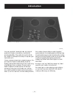
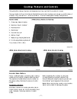
The new electronic cooktops make an eloquent
statement of style, convenience, and kitchen
planning flexibility. The electronic touch controls
are simple to understand and easy to operate–just
read and touch.
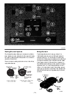
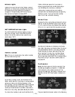
These cooktops include many helpful features. The
pan detection feature automatically shuts the
heating element OFF after 60 seconds of removing
a metallic pan from the heater. The pan sizing
feature adjusts the heated portion of the dual
element to fit the size of a metallic pan. And the
new warming feature keeps sauces and gravies
warm–or can be used as a normal heating element.
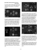
The controls lockout feature protects against
power activation to a heating element during times
of unintended usage or when cleaning the cooktop.
And the convenient kitchen timer can be used with
or without operating the heating elements to
simplify any kitchen task that requires a count-
down timer.
It’s easy to see how GE’s fresh ideas can make
anyone more creative in the kitchen!
The information on the following pages will help
you service these new electronic and electric
cooktops effectively and efficiently.
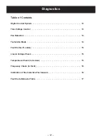
Содержание Profile JP938
Страница 19: ...17 Fault Code Behavior Table...
Страница 33: ...31 Notes...
Страница 34: ...32 Parts List...
Страница 36: ...34...
Страница 38: ......
Страница 39: ......