background image

Courtesy of NationalSwitchgear.com

Содержание POWER/VAC 4.16

Страница 1: ...RUCTIONS SUPERSEDES GEK 39672E POWER VAC METAL CLAD SWITCHGEAR TYPES 4 16 AND 13 8 FOR POWER VAC CIRCUIT BREAKER TYPES VB 4 16 VB 7 2 VB 13 8 VB1 4 16 AND VB1 13 8 GENERAL ELECTRIC Courtesy of Nationa...

Страница 2: ...d and Test Device 17 17 17 17 18 18 18 19 19 19 19 19 20 20 Installation Location Anchoring Indoor Equipment Floor Preparation Outdoor Equipment Outdoor Equipment With Protected Aisle Outdoor Equipmen...

Страница 3: ...e Interlock Spring Discharge Interlock Interference Interlock ClosingSpring Gag Interlock Key Lock Padlocks Stationary AuxiliarySwitch Breaker Position Switch Space Heaters Maintenance Recommended Mai...

Страница 4: ...Joint TeeConnection Joint Double Bus Bar Joint Pothead or Bushing or Terminator 6 CableTermination Joint Insulation Materialsfor Field Installation 5kV 15kV Bus Duct Gasket Installation of Primary Cab...

Страница 5: ...with this equipment The following practices should be included in a user s safety program These do not supplant the user s responsi bility for devising a complete safety program They are rather sugge...

Страница 6: ...Q in oo Ov 00 5 u Fig 1 Typical Indoor Power Vac Metal Clad Switchgear Equipment Typical Outdoor Power Vac Metal Clad Switchgear Equipment Fig 2 6 Courtesy of NationalSwitchgear com...

Страница 7: ...as been de energized all control power must must be disconnected before servicing 2 All spring charged mechanisms related to a breaker must be serviced only by skilled and knowledgeable personnel capa...

Страница 8: ...TIMBER LIFT JACK 4 CORNERS EYE O LIFTING ANGLE f 1 i9 i r t E A i SEE OPTIONAL METHODS O A I o I 1 I FLOOR LINE 2 Q IT TT Al AA ROLLERS IF USED OPTIONAL METHOD IN THIS DIRECTION ONLY USE ROLLERS FOR M...

Страница 9: ...ompany the claim STORAGE OF INDOOR EQUIPMENT If it is necessary to store the equipment for any length of time the following precautions should be taken to prevent breakage corrosion damage or deterior...

Страница 10: ...and primarycable compartment Remove all cartons and other miscellaneous materials packed inside units before energizing any heaters If the equipment has been subjected to moisture it should be carefu...

Страница 11: ...FRAME FINISH FLOOR 3 0o SWITCHGEAR PAD 0 REAR PAD J 1 LINE 35 RECOMMENDED FOR REAR HINGED COVFRS 5EL m i 4 fo 0 t THREADED INSERT IN CONCRETE ANCHORS USE EXPANSION NBOLTSi C 4 CHANNEL SWITCHGEAR FLOO...

Страница 12: ...ASM S WITH BUBBLE ADDED ON LIFT SLING SPREADER V SPREADER X T y n 11 r J LIFT ANGLE O t v o I I i LIFTING STRUCTURE i 1 u 4 1 i I S i SUPPORT SHIPPING STRUCTURE I N t ft L 4 r oc u AISLE ASM TYP AISLE...

Страница 13: ...t AISLE FLOOR f METAL CLAD sEQUIPMENT FLOOR FINISH FLOOR DETAIL VIEW r ROOF CAP I I CHANNEL END CAP END CAP ROOF i i CHANNEL END CAP AISLE ROOF APPLY CLEAR SEAL ON s VERTICAL JOINT EQUIPMENT ROOF i x...

Страница 14: ...OF ROOF CAP I G 1 r 5 u l PRESS TITE ANGLE cC END CAP i CHANNEL END CAP END CAP i N i ROOF i oo METAL CLAD EQUIPMENT METAL CLAD EQUIPMENT s 2 o END CAP O PRESS TITE 4 rN O EQUIPMENT PANEL 7 i COMMON A...

Страница 15: ...door upand the bottom to the right place a pry bar behind the hinge near the bottom of the door and pull forward as shown in Fig C Extreme caution must be used not to spring the hinge To move the top...

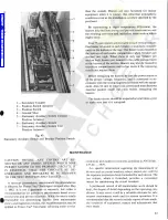
Страница 16: ...aker Compartment 3 Load Take Offs 4 Secondary Compartment Side Section View Power Vac Metal Clad Switchgear U oo m 00 ON 00 o oo I Lift Truck 2 Breaker 3 Rails 4 Interlock Power Vac Breaker and Lift T...

Страница 17: ...s between vertical sections Power Vac circuit breakers of the same rating are inter changeable in their corresponding metal clad units An interference interlock is provided on the rear of each circuit...

Страница 18: ...RACKING OPERATOR The optional electrically operated racking device see Fig 11 provides a convenient means for racking a breaker be tween the connected and test positions from a remote loca tion It is...

Страница 19: ...ted with an extruded thermoplastic insulation sleeving or an applied epoxy insulation using the fluidized bed process All bolted joints have silver to silver connections for low contact resistance Mos...

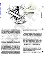
Страница 20: ...S WHEN THE DEVICE IS INSTALLED IN AN UPPER COMPARTMENT AND TO THE UPPER STUDS WHEN THE DEVICE IS INSTALLED IN A LOWER COMPARTMENT Refer to Fig 9 which shows a side section view of the switchgear for c...

Страница 21: ...nd more than 3 inches beyond the front of the equip ment OUTDOOR EQUIPMENT Switchgear support should be concrete or reinforced con crete with depth fill drainage etc according to recom mended foundati...

Страница 22: ...21 00 END WALL REUSE 1 4 20 HARDWARE SHIPPING COVERS AISLE END EXTENSION U i iN T SHIPPING SUPPORT V AISLE WALL SHIPPING POSITION G AISLE INSTALLATION T Fig 16 3 16 1 0282 A 4527 DETAIL VIEWS SHOWN ON...

Страница 23: ...WITH FILTER FOR AISLE END WALL DESIGN S3 a TYPICAL ROOF ANGLE REUSE HARDWARE 21 5 00 H ON FLOOR CAP t 11 2 PRESTITE GASKET FLOOR TIE PLATE j 1 L I Fig 16 9 r AISLE END WALL AISLE END EXTENSION A Fig 1...

Страница 24: ...SHER 3 8 16 BOLTx LG WASHER LOCKWASHER 1 4 20 BOLT X LG WASHER LOCKWASHER 3UUC GASKET O O GASKET NUT NUT ROOF PANEL NUT ASSEMBLY OF DETAILS P N ASSEMBLY OF DETAILS J K DETAIL R WITH END CAP REMOVED AN...

Страница 25: ...port from aisle end wall 5 Position aisle end extension s and or aisle end wall s at ends of the line up Secure aisle extension to aisle floor and metal clad Fig 16 5 detail A B H G Secure aisle end w...

Страница 26: ...b indicates that special procedures required to add new metal clad units to outdoor equipment without a pro tected aisle and Fig 18a indicates the special precedures required to add new metal clad uni...

Страница 27: ...LE ASSEMBLY BOLT IN PLACE 3 ASSEMBLE NEW ROOF CAP CHANNEL END CAP 4 ASSEMBLE NEW FLOOR TIE PLATE 5 REASSEMBLE ITEMS A 1 THROUGH A 5 Fig 18a Outdoor Metal Clad Switchgear Addition of Units to a Line up...

Страница 28: ...plating is not covered by insulation e g ground bus and ground risers the D50H47 must be applied to overlap this interface for a minimum of 1 2 inch Finally after the connection bolts have been tight...

Страница 29: ...ust be deburred and smoothed before applying tape STEP B OUTERWRAP 5 15kV Apply two 2 layers 1 2 lap of high voltage tape 0282A3529 P 4 2 wide mastic side down maintain ing a medium A tension on the t...

Страница 30: ...1TC15 000V 5 6 4 6 9 10 11 12 NOTE APPLY 3 LAYERS A LAP FOR CONDUCTORS PASSING THROUGH C TS NOTE APPLY TAPE AT MEDIUM TENSION TO PRODUCE A VOID FREE UNIFORM BUILD UP OF TAPE A MEDIUM TENSION THINS A 0...

Страница 31: ...IC SIDE DOWN A Fig 29 Pothead or Bushing or Terminator Fig 27 Tee Connection Joint 4 WIDE PAD H V TAPE 0 MA B R B PUTTY FRAMEWORK r i Mi C MIN C MIN A EPOXY INSULATION FLUID DIP THERMOPLASTIC SLEEVING...

Страница 32: ...sembled and insulated as described above for main buses Adjustable joints are provided in long runs of bus duct to allow for variations in building construction etc These joints should be loosened bef...

Страница 33: ...le of terminating a shielded cable is shown in Fig 34 If the cable is aluminum the conductor surface must be carefully abraded and the cable covered liberally with a joint compound recommended by the...

Страница 34: ...termination is inside the metal clad enclosure the Indoor Type A system isgenerally applicable If excessive contamination is a problem the padmount type G system may be desirable No matter which syste...

Страница 35: ...terminal blocks in accordance with the wiring diagrams furnished for the requisition The cables from the control power source to the switch gear should be large enough to avoid excessive voltage drop...

Страница 36: ...ratus and Service Engi neering office for instructions Failure to adhere to the fol lowing instructions could result in serious injury The operation of the breaker with its associated devices may be t...

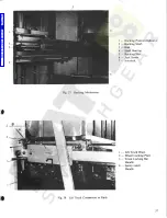
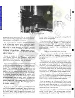
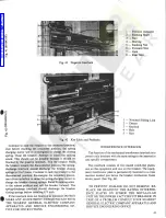
Страница 37: ...il 4 Shaft Bearing 5 Racking Nut 6 Jack Screw 7 Interlock Fig 37 Racking Mechanism 1 Lift Truck Brace 2 Wheel Locking Plate 3 Truck Locking Bar Handle 4 Safety Latch Handle Fig 38 Lift Truck Connectio...

Страница 38: ...its blocking position before lifting the breaker from the ground See GEK 90214 To load the breaker onto the lift truck extend each dock ing interlock bar 1 by slightly depressing the track roller bloc...

Страница 39: ...the door then attempt to insert the racking handle into the hole in the unit door A definite stop should be encountered preventing the socket on the racking handle from engaging the racking mechanism...

Страница 40: ...the above mentioned positions and prevent recharging by opening the close latch monitoring switch in the breaker spring charging circuit To test the function of the spring discharge interlock in stal...

Страница 41: ...closing springs Raise th racking arms to the release position and roll the breaker forward The spring discharge interlock should discharge the breaker closing springs before traveling 1 2 inch If the...

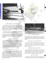
Страница 42: ...k see Fig 41 To remove the key 3 push slide 1 to the rear and extend the bolt 4 of the lock into slot This allows the key to be re moved and prevents the breaker from closing The key lock does not pre...

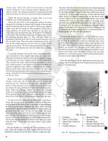
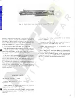
Страница 43: ...ct Position Actuator 6 Stationary Auxiliary Switch 7 Stationary Auxiliary Switch Test Position Actuator Fig 45 Stationary Auxiliary Switch and Breaker Position Switch MAINTENANCE CAUTION BEFORE ANY CO...

Страница 44: ...ssembly and replaced if any signs of deterioration are evident INDOOR AND OUTDOOR ACRYLIC PAINT FINISH The outside of outdoor switchgear has an acrylic paint finish providing improved resistance to al...

Страница 45: ...orrect spraying viscosity When paint is received in less than five gallon quantities the paint has been factory thinned Both the primer and paint should be applied only when the temperature is above 5...

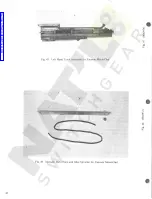
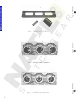
Страница 46: ...os N s 00 r TJ oo E Fig 47 Left Hand Track Assembly for Vacuum Metal Clad t N r Os N O 00 00 00 UH Fig 48 Spreader Bar Chain and Idler Sprocket for Vacuum Metal Clad 46 Courtesy of NationalSwitchgear...

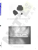
Страница 47: ...o m r N o 00 is op U Fig 49 Connection Boots for Primary Disconnects Surge Suppressors and Bus o r o m S oo o oo Fig 50 Polyester Inter Unit Barrier L 47 Courtesy of NationalSwitchgear com...

Страница 48: ...m O 00 00 U Porcelain Inter Unit Barrier r o rn o oo N r i 00 UH Fig 52 Polyester Primary Disconnect Porcelain Primary Disconnect Fig 53 48 Courtesy of NationalSwitchgear com...

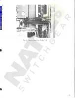
Страница 49: ...00 P ON rvj O oc 00 Fig 54 Vacuum Metal Clad Breaker Unit 49 Courtesy of NationalSwitchgear com...

Страница 50: ...GENERAL ELECTRIC COMPANY SWITCHGEAR OPERATION BURLINGTON IOWA 52601 GENERAL ELECTRIC PRINTED IN U S A 4 84 Courtesy of NationalSwitchgear com...

Отзывы: