Copyright 2009
Induction Flow Chart
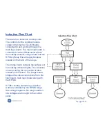
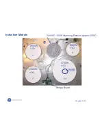
There are four induction cooktop coils.
The controls for the cooktop module
consist of two burner Touch Boards
connected to and working through the
main logic board. The main logic board is
connected via the LINbus serial wire to
the cooktop module, bridge board and the
RPSM. (Relay Power Supply Module)
located on the back of the range.
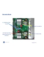
The bridge board contains the surface on/
hot cooktop indicator lights. The induction
module cooling fan connection is also
located on this board. The bridge board
bridges the Linbus connections from the
filter board, main logic board along with
the RPSM.
A Fifth cooktop element is a resistive
warmer controlled by the RPSM relays.
See wiring diagrams. No relay boards or
line voltages are brought to the control
panel.
Содержание PHB925SP1SS
Страница 2: ...Copyright 2009 Warranty...
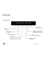
Страница 4: ...Copyright 2009 Nomenclature...
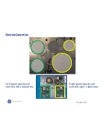
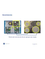
Страница 12: ...Copyright 2009 Element Operation Filter board controls both left and right generator boards...
Страница 16: ...Copyright 2009 Rear Component Layout...
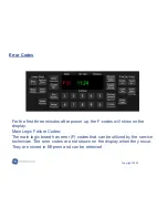
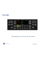
Страница 20: ...Copyright 2009 After selecting 1 for the oven the log is shown Error Codes...
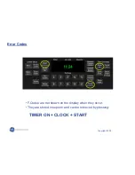
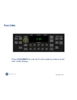
Страница 23: ...Copyright 2009 Press CLEAR OFF to exit the F Code mode and return to the time of day display Error Codes...
Страница 24: ...Copyright 2009 Oven Error Codes...
Страница 32: ...Copyright 2009 Induction Module The induction module can now be gently removed from the cooktop...


