


Chapter 3. Configuration
74
PACSystems* RX3i & RSTi-EP PROFINET IO-Controller User Manual
GFK-2571N
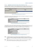
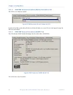
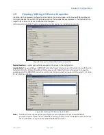
3.7.5.2
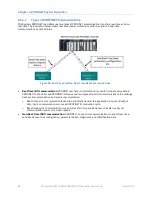
The Change Submodule List
On the
Change Submodule List
, select the type of inputs or outputs that will be wired to the module, and drag
the selection to the
Content
field in the left pane. For example:
Figure 70: Selecting the Sub-Module Configuration with Jumper Settings Declared
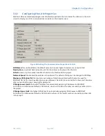
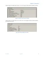
Once the
Content
field has been populated, the
Description
field indicates how the physical jumpers in the
module should be configured. The +10 Vdc analog inputs selected in Figure 70 do not require the installation of
jumpers on the module. If selected, the other choices for this particular module would require jumpers. It is
important to ensure that the jumper installation matches the configuration for that module in PME. In the
event the jumper settings need to be altered due to changing channel requirements, the module configuration
in PME should be changed to match by retracing the steps outlined in this section.
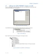
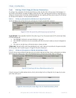
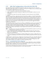
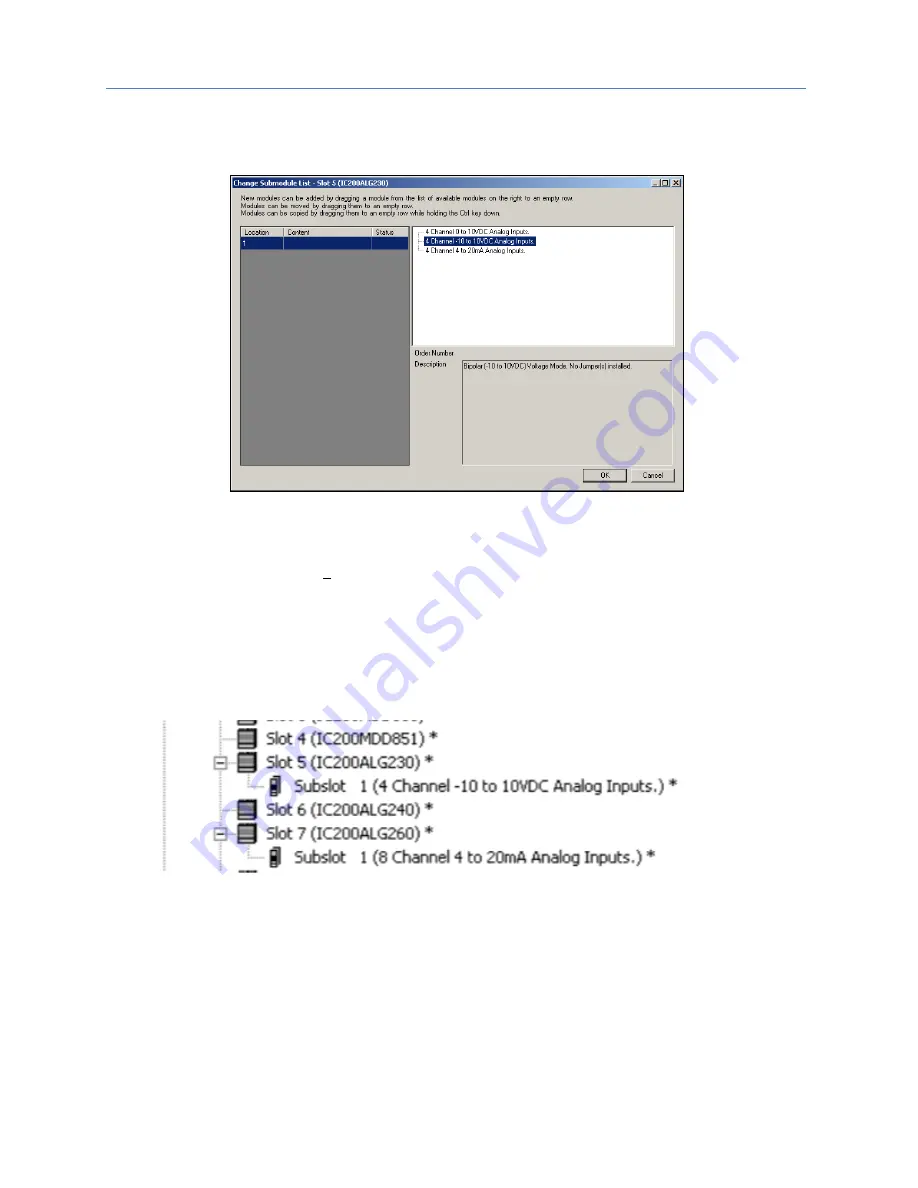
After choosing the submodule parameters of the module as described above, a subslot appears in the
Navigator
, and the module’s
Configuration Mismatch
is cleared:
Figure 71: Analog Modules Showing Configuration Mismatch Cleared
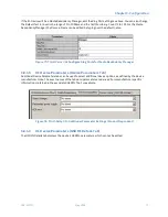
3.7.5.3
Configuring the Module Parameters
Double-click the subslot (not the module slot) in the
Navigator
to configure the module parameters. The
remaining configuration steps for these modules is the same as for other VersaMax modules.
For a list of VersaMax Analog module subslot configuration choices and jumper settings, refer to
Configuring
Analog Modules that Have Jumpers
in the
VersaMax PROFINET Scanner Manual,
GFK-2721.


