

All GE ranges are equipped with
an Anti-Tip device. The installation
of this device is an important,
required step in the installation
of the range.
Specification Revised 9/15
For answers to your Monogram
®
, GE Profile
™
Series
or GE
®
Series appliance questions, visit our website
at geappliances.com or call GE Answer Center
®
service, 800.626.2000.
P2B940SEJ
GE Profile
™
Series 30" Dual-Fuel Free-Standing Convection Range with Warming Drawer
ElEctrical rating:
240V, 60Hz, 30A
inStallation information:
Before installing,
consult installation instructions packed with product for current
dimensional data.
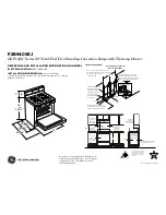
DimEnSionS anD inStallation information (in inchES)
Minimum to
cabinets on
either side
of the range.
Minimum
clearance
to left wall
Minimum
Minimum
clearance to
right wall
Maximum
depth for
cabinets above
countertops
Front edge of
the range side
panel forward
from cabinet
To cabinets below cooktop
and at the range back
To cabinets
below
cooktop and
at the range
back
18"
6"
30"
30"
15"
6"
36"
0"
0"
1/4"
7-1/2
8
9
4
30
3
3
3
2-1/4
2
NOTE: Make gas connections on
the left side and electrical connections
on the right side of the
cutout opening.
Recommended acceptable
electrical outlet area. Orient
the electrical receptacle so the
length is parallel to the floor.
Wall-Mounted
Recommended area
for through-the-wall
connection of pipe
stub/shut-off valve.
Recommended area for
through-the-floor connection
of pipe stub/shut-off valve.
This area allows
flush installation
to rear wall.
GAS PIPE AND ELECTRICAL
OUTLET LOCATIONS
46 1/4"
28 3/4"
w/ handle
26 1/4"
w/o handle
30"
11 1/4"
36"
to
36 1/2"
SINGLE OVEN GAS RANGE