Содержание MicroVersaTripPlus AK-50

Страница 1: ...ng the latest techno logical advancement in GE trip systems MicroVersaTrip Plus and MicroVersaTrip PM Conversion Kits are designed and breaker tested to conform with ANSI Standard C37 59 allowing the...

Страница 2: ...unications Harness 4 11 4 5 8 9 10 11 SECTION 4 BACK FRAME CONVERSION Modifying the Crossbar Installing Phase Sensors 12 14 12 13 14 SECTION 5 FOUR WIRE GROUND FAULT OPTION Stationary Breaker Conversi...

Страница 3: ...pting any installation maintenance or modification Follow all lock out and tagging rules of the National Electrical Code and all other applicable codes Do not work on a closed breaker or a breaker wit...

Страница 4: ...rically operated breakers with EC trip devices 3 Installing the flux shifter and trip paddle 4 Installing the programmer mounting bracket 5 Installing the programmer wire harness 6 Installing the comm...

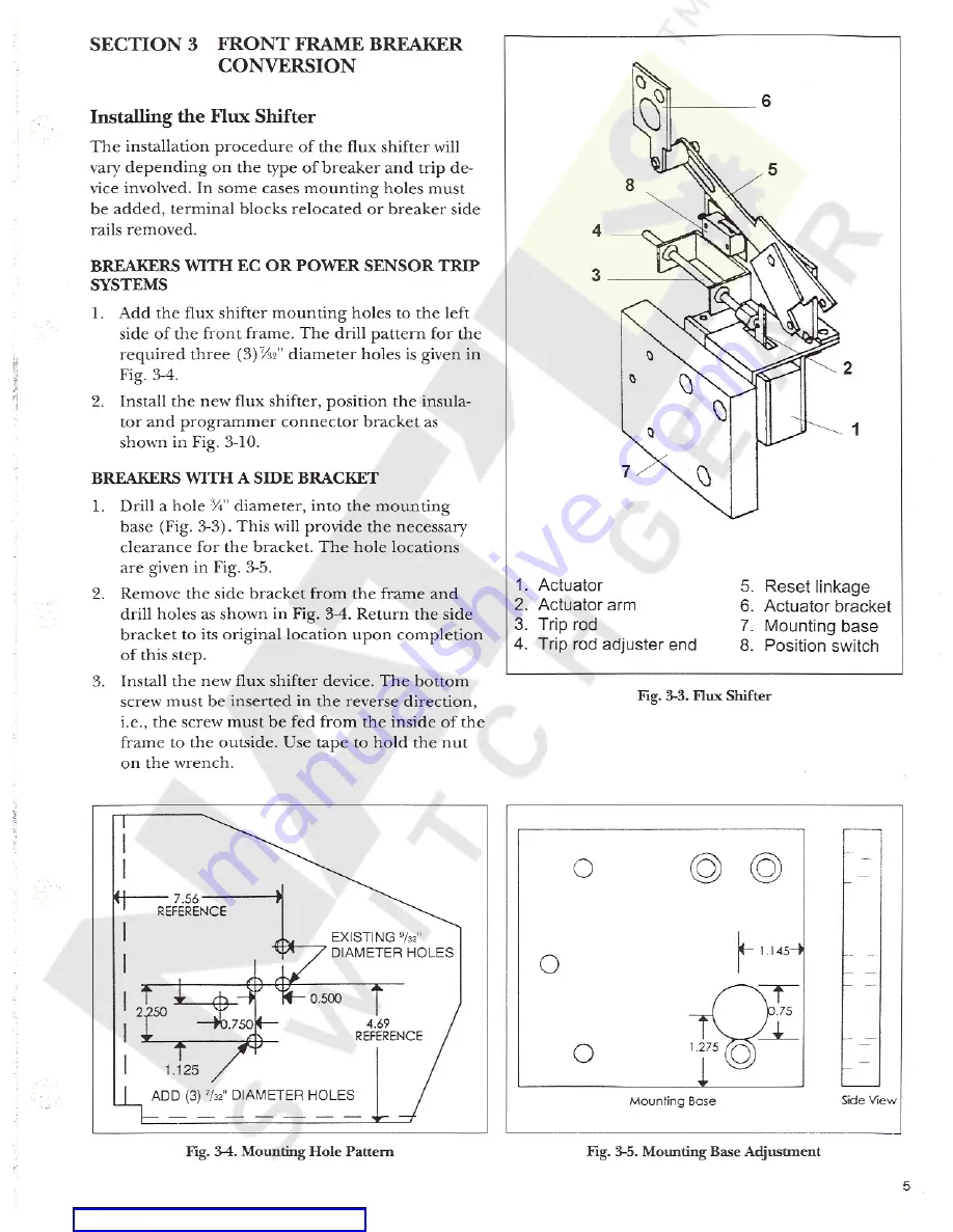
Страница 5: ...connector bracket as shown in Fig 3 10 BREAKERS WITH A SIDE BRACKET Drill a hole diameter into the mounting base Fig 3 3 This will provide the necessary clearance for the bracket The hole locations a...

Страница 6: ...wire Wire splice 12 butt splices Wire labels Drill and size F drill bit is 18 tap Flathead screwdriver Two r i6 18 bolts and lock washers To remount the terminal block Step 1 Drill and tap two 2 holes...

Страница 7: ...T TRIP SYSTEMS Step 1 Remove the ECS or SST Programmer Step 2 Remove the existing flux shifter device and the pro grammer control harness Step 3 Install the new flux shifter device positioning the ins...

Страница 8: ...e and the end of the flux shifter rod at 0 100 inches Use a 0 100 inch diameter rod not supplied as shown in Fig 3 12 Set the adjuster end of the trip rod and lock it in place with the jam nut Note th...

Страница 9: ...ig 3 14 If the manual indicator assembly busing on AJK 50 manual breakers interferes with the mounting bracket installation Fig 3 14 then the bracket will have to be modified This is accomplished by c...

Страница 10: ...e Route the harness under the flux shifter base At tach the harness to this base using the wire keepers provided Install the programmer harness as shown in Fig 3 10 Include the flux shifter leads with...

Страница 11: ...l type breakers Figures 3 20 through 3 21 are representative examples of harness connections and routing directions They are not meant to be all inclusive A caution label Fig 3 22 should be mounted on...

Страница 12: ...x shifter s reset linkage is driven by the ac tuator bracket See Fig 3 3 The actuator bracket must be assembled to the left side link of the left pole as shown in Fig 4 1 If the actuator bracket mount...

Страница 13: ...4 Fig 4 3 Lower Adapter Connector AK 50 AKS 50 BREAKERS WITH SST TRIP SYSTEMS Step 1 Replace the existing SST phase sensor with the new MicroVersaTrip phase sensor provided Step 2 Install as shown in...

Страница 14: ...MicroVersaTrip RMS 9 sensors mount on the upper breaker studs The sensors are held on the stud with the locking rings as shown in Fig 4 5 Leave enough of the stud exposed for the primary fingers to e...

Страница 15: ...ERMINAL BOARD i MOUNTING HARDWARE 4 TYPES AK 50 AKS 50 STATIONARY BREAKERS The 4th wire disconnect for stationery breakers con sists of terminal board mounted to the lower front channel as shown in Fi...

Страница 16: ...o the breaker Figures 5 3 5 4 depict the two designs The Conversion Kit contains an assembled ready to install mounting block and bracket for AKD 5 or AKD 6 installation plus a bracket only for type A...

Страница 17: ...WHITE COMMON WHITE WIRE BLACK WIRE GREEN I TIE MOUNTING HOUSING Ol P lO Oi MOUNTING HOUSING I WHEN USED THE 4TH WIRE NEUTRAL SENSOR DISCONNECT BLOCK MOUNTS ON TOP OF TAP TERMINAL BOARD VIA ITS 2 LOWE...

Страница 18: ...the phase sen sors the taps on the neutral sensor must be corre spondingly positioned For kits with fixed phase sen sors be sure to use the corresponding tap on the neutral sensor Mount the neutral s...

Страница 19: ...IA HOLES MAX STRAP 1 25 MAX STRAP 3 33 ref 1 25 I i i i V i 1 625 m 625 I I 1 18 ref TERMINAL BLOCK 1 75 1 75 88 4 75 I GI T I GI 3 75 MAX I GI 1 75 3 25 I GI y V p I CGI 11 25 Fig 5 7 Neutral Sensor...

Страница 20: ...r applica tions are supplied in the conversion kit See Figs 6 1 through 6 5 for mounting diagrams 229 230 231 232 233 i 235 1 236 i 237 238 239 CENTER LEFT PHASE SENSOR TERMINAL BOARD PHASE SENSOR TER...

Страница 21: ...TER HOLES IN COMPARTMENT REAR OF BREAKER 230 6 00 232 235 235 225 233 246 238 A 237 226 i m 231 246 i i i f 3 75 0 44 5 12 0 88H 7 COMPARTMENT 8 62 SIDE VIEW OF COMPARTMENT VIEW LOOKING AT REAR OF COM...

Страница 22: ...ogrammer This will engage the connectors and release the locking lever which will move upwards Step 2 Verify that the locking lever actually engaged the programmer pin To remove the programmer move lo...

Страница 23: ...est kit Cat No TVTS1 or TVRMS on this programmer False Tripping Breakers Equipped with Ground Fault When nuisance tripping occurs on breakers equipped with the ground fault trip element a probable cau...

Страница 24: ...d secondary discon nect block Also check for continuity from the breaker mounted neutral secondary disconnect block through to the female harness connector If the breaker s lowrer studs connect to the...

Страница 25: ...ONNECTIONS FOR GROUND FAULT OPTION ONLY 9 68 0 02 O4 05 R W H E COMM NET I D T 24Vdc POWER E ABC 30 VOLTAGES J il t w 9 O r 0 x1 C FLUX SHIFT TRIP DEVICE 0 CONNECTIONS FOR COMMUNICATIONS OPTION ONLY I...

Страница 26: ...tion or maintenance Should further information be desired or should particular problems arise which are not covered sufficiently for the purchaser s purposes the matter should be referred to the GE Co...

Отзывы: