We would like to highlight the following changes of nomenclature however:
●
The word 'relay' is no longer used for the device itself. Instead, the device is referred to as an 'IED'
(Intelligent Electronic Device), the 'device', the 'product', or the 'unit'. The word 'relay' is used purely to
describe the electromechanical components within the device, i.e. the output relays.
●
British English is used throughout this manual.
●
The British term 'Earth' is used in favour of the American term 'Ground'.
2.4
PRODUCT SCOPE
This product protects busbars with up to 4 zones plus a check zone. It can be applied at any voltage level.
One device is used to protect each phase (3-box solution). A further device can be used to protect the
neutral line (4-box solution). The device is suitable for applications on solidly grounded systems, or where a
centralised scheme is needed.
Each device can manage a maximum of:
●
4 Voltage transformers (VTs) (1 VT per zone),
●
18 Current transformers (CTs)
●
18 Circuit breakers (CBs)
●
72 isolators
●
Up to 40 Digital Inputs and 128 Virtual Inputs (128 digital inputs via communications) for each
protected phase
●
Up to 32 Digital Outputs and 128 Virtual Outputs (128 digital outputs via communications) for each
protected phase
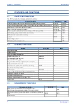
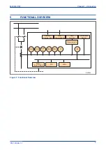
The P747 consists of the following main components.
Main protection
This uses low impedance biased current differential protection. The typical operating time is less than one
cycle. If a fault occurs and more than one zone needs to be tripped, you might need to trip zones
sequentially. You can do this by setting different time delays on each of the zone differential elements.
Backup protection
This consists of:
●
phase overcurrent
●
dead zone
●
circuit breaker failure
Settings application software
This allows you to create a scheme and display the measured data. The scheme editor allows you to quickly
draw schemes from a library of elements, then validate the scheme. It can also display the status of DDBs
and measured data on the scheme in real time.
Inputs and outputs
The device has many hard-wired digital inputs and outputs. For applications that demand more, virtual inputs
and outputs can be used between the products protecting the different phases. 128 virtual inputs and outputs
can be shared between products using communications links. Use hard-wired inputs and outputs to connect
the most time-critical signals between devices. Use Virtual inputs and outputs to communicate less time-
critical information signals between devices.
MiCOM P747
Chapter 1 - Introduction
P747-TM-EN-1
5
P747-TM-EN-1.1
Содержание MiCOM P747 Agile
Страница 2: ......
Страница 16: ...Contents MiCOM P747 xiv P747 TM EN 1 P747 TM EN 1 1...
Страница 20: ...Table of Figures MiCOM P747 xviii P747 TM EN 1 P747 TM EN 1 1...
Страница 21: ...INTRODUCTION CHAPTER 1...
Страница 22: ...Chapter 1 Introduction MiCOM P747 2 P747 TM EN 1 P747 TM EN 1 1...
Страница 31: ...SAFETY INFORMATION CHAPTER 2...
Страница 32: ...Chapter 2 Safety Information MiCOM P747 12 P747 TM EN 1 P747 TM EN 1 1...
Страница 42: ...Chapter 2 Safety Information MiCOM P747 22 P747 TM EN 1 P747 TM EN 1 1...
Страница 43: ...HARDWARE DESIGN CHAPTER 3...
Страница 44: ...Chapter 3 Hardware Design MiCOM P747 24 P747 TM EN 1 P747 TM EN 1 1...
Страница 74: ...Chapter 3 Hardware Design MiCOM P747 54 P747 TM EN 1 P747 TM EN 1 1...
Страница 75: ...CONFIGURATION CHAPTER 4...
Страница 76: ...Chapter 4 Configuration MiCOM P747 56 P747 TM EN 1 P747 TM EN 1 1...
Страница 117: ...PROTECTION FUNCTIONS CHAPTER 5...
Страница 118: ...Chapter 5 Protection Functions MiCOM P747 98 P747 TM EN 1 P747 TM EN 1 1...
Страница 160: ...Chapter 5 Protection Functions MiCOM P747 140 P747 TM EN 1 P747 TM EN 1 1...
Страница 161: ...MONITORING AND CONTROL CHAPTER 6...
Страница 162: ...Chapter 6 Monitoring and Control MiCOM P747 142 P747 TM EN 1 P747 TM EN 1 1...
Страница 211: ...SCADA COMMUNICATIONS CHAPTER 7...
Страница 212: ...Chapter 7 SCADA Communications MiCOM P747 192 P747 TM EN 1 P747 TM EN 1 1...
Страница 259: ...REDUNDANT ETHERNET CHAPTER 8...
Страница 260: ...Chapter 8 Redundant Ethernet MiCOM P747 240 P747 TM EN 1 P747 TM EN 1 1...
Страница 293: ...CYBER SECURITY CHAPTER 9...
Страница 294: ...Chapter 9 Cyber Security MiCOM P747 274 P747 TM EN 1 P747 TM EN 1 1...
Страница 313: ...SETTINGS APPLICATION SOFTWARE CHAPTER 10...
Страница 314: ...Chapter 10 Settings Application Software MiCOM P747 294 P747 TM EN 1 P747 TM EN 1 1...
Страница 322: ...Chapter 10 Settings Application Software MiCOM P747 302 P747 TM EN 1 P747 TM EN 1 1...
Страница 323: ...BUSBAR COMMISSIONING TOOL CHAPTER 11...
Страница 324: ...Chapter 11 Busbar Commissioning Tool MiCOM P747 304 P747 TM EN 1 P747 TM EN 1 1...
Страница 330: ...Chapter 11 Busbar Commissioning Tool MiCOM P747 310 P747 TM EN 1 P747 TM EN 1 1...
Страница 331: ...SCHEME LOGIC CHAPTER 12...
Страница 332: ...Chapter 12 Scheme Logic MiCOM P747 312 P747 TM EN 1 P747 TM EN 1 1...
Страница 348: ...Chapter 12 Scheme Logic MiCOM P747 328 P747 TM EN 1 P747 TM EN 1 1...
Страница 349: ...INSTALLATION CHAPTER 13...
Страница 350: ...Chapter 13 Installation MiCOM P747 330 P747 TM EN 1 P747 TM EN 1 1...
Страница 361: ...COMMISSIONING INSTRUCTIONS CHAPTER 14...
Страница 362: ...Chapter 14 Commissioning Instructions MiCOM P747 342 P747 TM EN 1 P747 TM EN 1 1...
Страница 387: ...MAINTENANCE AND TROUBLESHOOTING CHAPTER 15...
Страница 388: ...Chapter 15 Maintenance and Troubleshooting MiCOM P747 368 P747 TM EN 1 P747 TM EN 1 1...
Страница 403: ...TECHNICAL SPECIFICATIONS CHAPTER 16...
Страница 404: ...Chapter 16 Technical Specifications MiCOM P747 384 P747 TM EN 1 P747 TM EN 1 1...
Страница 425: ...SYMBOLS AND GLOSSARY APPENDIX A...
Страница 426: ...Appendix A Symbols and Glossary MiCOM P747 406 P747 TM EN 1 P747 TM EN 1 1...
Страница 443: ...COMMISSIONING RECORD APPENDIX B...
Страница 444: ...Appendix B Commissioning Record MiCOM P747 424 P747 TM EN 1 P747 TM EN 1 1...
Страница 448: ...Final Checks Result LEDs reset Yes No Appendix B Commissioning Record MiCOM P747 428 P747 TM EN 1 P747 TM EN 1 1...
Страница 449: ...WIRING DIAGRAMS APPENDIX C...
Страница 450: ...Appendix C Wiring Diagrams MiCOM P747 430 P747 TM EN 1 P747 TM EN 1 1...
Страница 456: ...Appendix C Wiring Diagrams MiCOM P747 436 P747 TM EN 1 P747 TM EN 1 1...
Страница 457: ......


