GE Masoneilan VariPak 28001 Скачать руководство пользователя страница 21

Masoneilan VariPak Adjustable Cv Control Valves Instruction Manual  

|  21

Ref.

Qty

Part Name

Ref.

Qty

Part Name

Ref.

Qty

Part Name

Δ ☐ 

1

1 1/4" NPT pipe plug

   101

1 Grommet support plate

 140

1 Tubing

 Ο 

2

1 Seat-ring gasket

   102

1 Spring button


141  (a, b)

4 Screw


a

1 Seat ring Cv max. 3.8

   103

1 Locknut

 142

1 Output gauge


b

1 Seat ring Cv max. 2.3 and 1.2    104

2 Clevis

 143

1 Instrument gauge


3 

c

1 Seat ring Cv max. 0.25 and 

0.60

   105

1 Pivot pin No. 1

 144

1 Manifold block


d

1 Seat ring Cv max. 0.10

   106

1 Conical compression spring

 145

1 to 5 Shim


☐  

e

1 Seat ring Cv max. < 0.10


Ο 

107

1 Grommet

Ο 

   146

1 Gasket (includes 171 & 172)


☐ 

3


f

1 Spacer Cv max. < 0.10

   108

1 Actuator bracket

 147

1 Positioner block


4

1 Seat-ring retainer

   109

2 Cover screw

 148

2 Slotted flat. c screw


5

1 Packing spacer

   110

1 Cover

Ο 

 152

1 Positioner diaphragm S/A


Ο 

6

1 Packing ring


112 (a, b, c)

6 Retainer clip

Ο 

 153

1 O-ring


7

2 Packing flange stud

    114

1 Balance spring

♥ 

 154

1 Spring


8


a

2 Mounting nut


  115

1 Spring clamp

Ο 

 155

1 Sleeve


8


b

2 Packing flange nut


  116

1 Take-up screw

Ο 

 156

1 Spool


9

1 Packing follower


  117

1 Locknut

Ο 

 157

1 Spring


10

1 Packing flange


  118

1 Handwheel locknut

 158

1 Spring


11

1 Safety pin


  119

1 Handwheel bushing

Δ 159

2 Switch


12

a

1 Plug/stem Cv max. 3.8


  120

1 Handwheel

Δ 160

4 Screw

b

1 Plug/stem Cv max. 2.3


  121

1 Handwheel lock

Δ 161

4 Washer

c

1 Plug/stem Cv max. 1.2 & 0.6


  122

1 Lever arm stop

Δ 162

4 Nut

d

1 Plug/stemCv max. 0.25 & 0.10    123

1 Cover plug

Δ 163

4 Wire


13

  a

1 Body Cv max. < 3.8

   124

1 Pivot pin No. 4

Δ 164

1 Terminal


13

  b

1 Body Cv max. 3.8

   125

1 Locknut

■ 

165

2 Logo


18

1 Pivot pin No. 3 (22/108)

   126

1 Indicator

 168

1 Cover washer


20

1 I/P module

   127

1 Indicator plate

  170

2 Signal decal


21

1 Lever No. 1

   129

2 Indicator plate screw

■ 

 171

1 O-ring


22

1 Lever No. 2

   130

2 Speed nut

■ 

 172

1 O-ring


23

1 Adjustment pin

   131

1 Piston S/A

 173

1 Cover plug


24

1 Cv adjustment knob

   133

2 Serial plate screw

▼ 

180

1 Limit stop


25

1 Cv adjustment plate

   134

1 Actuator spring

▼ 

181

1 Locknut


26

2 Adjustment plate screw

   135

1 Serial plate

 182

1 Retaining ring (Cv max. <0.10)


27

4 Screw


Ο

 136

1 Diaphragm

 183

1 Plug (Cv max. <0.10)


Ο 

28

1 O-ring

   137

1 Diaphragm cover

 184

2 Pivot pin No. 2


Ο 

29

1 O-ring


  138

1 Union elbow t(incl. 138a)


Ο 

30

1 O-ring

   139

1 Cover cap screw

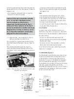
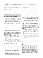
Figure 24 - Cross-section of the VariPak 28002 adjustable-Cv actuator and the 7700P positioner

PARTS LIST

Ο 

Recommended spare parts

  Complete subassembly includes: plug and stem (183), 

retaining ring (182), seat ring (3e) and spacer (3f) (see 

figure 2).

 Only for pneumatic positioner.

 See Figure 2.

 See table in figure 23.

 Only for handwheel (optional) (fig. 5).

Ο

  Complete subassembly includes Ref. Nos. (155, 156 

and157).

■ 

Not shown.

 Only for cast bodies.

  Only on actuator with handwheel and/or Model 8013 

E.P. positioner (fig. 5).

Δ

  Only for optional limit-switch adaptation: quantity 

given for two limit switches (see fig. 13).

Содержание Masoneilan VariPak 28001

Страница 1: ...GE Oil Gas 28000Series Masoneilan VariPak Adjustable Cv Control Valves Instruction Manual...

Страница 2: ...ENT AT THE SITE THESEINSTRUCTIONSDONOTPURPORTTOCOVERALLDETAILSORVARIATIONSINEQUIPMENT NOR TO PROVIDE FOR EVERY POSSIBLE CONTINGENCY TO BE MET IN CONNECTION WITH INSTALLATION OPERATION OR MAINTENANCE S...

Страница 3: ...10 3 3 Pneumatic and Electrical Circuit 11 3 4 Limit Switches 11 4 Calibration 12 4 1 Piston Rod Clevis Adjustment 12 4 2 Plug Stem Adjustment 12 4 3 Limit Stop Adjustment 13 4 4 Varipak 28002 Cv Adju...

Страница 4: ...T GE has a highly skilled After Sales Department to assist customers with start up maintenance and repair of valves and instruments Contact your nearest GE Sales Office or Representative or the After...

Страница 5: ...ly be calibrated on site between 0 004 and 0 010 2 2 FLOW COEFFICIENT OF VARIPAK 28001 SINGLE LEVER AND 28002 ADJUSTABLE Cv VALVES 2 2 1 Plug seat ring combinations trim Eight plugs and five seat ring...

Страница 6: ...ation The plug and seat ring combination can be changed very easily for trim Nos 1 to 9 inclusive Simply replace the following parts The plug and seat ring see figures 1 and 2 to select the combinatio...

Страница 7: ...adjustment knob again firmly Note This operation entails moving lever No 2 either pneumatically by allowing air into the actuator or manually by pressing piston clevis 140b with a screwdriver or simi...

Страница 8: ...w 116 Unhook spring 114 from spring clamp 115 2 5 1 VariPak 28001 single lever valve E Remove retainer clips 112b from pin 18 and remove the pin from lever 113 and plug clevis 104a Note This operation...

Страница 9: ...over 110 using the two screws 109 If the valve is equipped with a handwheel refit the cover and turn the handwheel clockwise so that it engages in lever arm stop 122 Tighten cover screws 109 N Put the...

Страница 10: ...ed stainless steel All the line bolting required for installation can be supplied by GE on request Figure 7 VariPak flanged connection Connected by 25 mm flanges machined to standards ISO PN 20 50 and...

Страница 11: ...heck that the supply pressure is that indicated on the serial plate 7700P or 7700E positioners can be installed on both VariPak 28001 single lever and VariPak 28002 adjustable Cv valves Figure 11 Conn...

Страница 12: ...st indicator Check that indicator 126 is correctly positioned Release air pressure 4 1 2 Adjusting the piston rod clevis on the Figure 14 Piston rod clevis 104b adjustment VariPak 28002 adjustable Cv...

Страница 13: ...the air pressure after inserting the shim At this closing point where the plug is not tightened onto the seating the slides of levers No 1 and 2 should be perfectly parallel This characteristic makes...

Страница 14: ...in the valve actuator or positioner before maintenance or disassembly 5 1 ACTUATOR DIAPHRAGM REMOVAL Figures 17 24 25 26 and 27 A Unscrew the two pressure connection nuts 138a and pull tubing 140 out...

Страница 15: ...ely loosen locknut 117 and screw 116 Remove spring clamp 115 from lever No 2 and remove balance spring 114 from the positioner E Remove the retainer clip 112b from each of the two pins 184 and disenga...

Страница 16: ...t ring 3e until the stem slides smoothly Fit spacer 5 turning it so that one of its holes is aligned with safety pin 11 hole in the valve body Note For valves with a maximum Cv less than 0 10 check th...

Страница 17: ...ever No 2 where spring clamp 115 is fitted is located above and in line with balance spring 114 I Fit adjustment pin 23 in the slide of lever No 1 and screw adjustment knob 24 on its threaded end Inse...

Страница 18: ...ved while the valve is still pressurized The internal parts of the valve cannot be removed unless the safety pin is removed first Remove the two packing flange nuts 8b and back off the two actuator br...

Страница 19: ...and its three O rings spring 158 and manifold block 144 Tighten the screws 141a refit tubing 140 and tighten pressure connection nuts 138a Note The ports in gasket 146 must be aligned with those in t...

Страница 20: ...parts Otherwise simply check that parts are in perfect condition before refitting Caution Handle the shims carefully 145 C If the parts mentioned above have been removed proceed as follows Fit the O...

Страница 21: ...1 4 Washer c 1 Plug stem Cv max 1 2 0 6 122 1 Lever arm stop 162 4 Nut d 1 Plug stemCv max 0 25 0 10 123 1 Cover plug 163 4 Wire 13 a 1 Body Cv max 3 8 124 1 Pivot pin No 4 164 1 Terminal 13 b 1 Body...

Страница 22: ...22 GE Oil Gas 180 181 Figure 25 Cross section of the VariPak 28001 single lever actuator and the 7700E positioner Figure 26 Partial cross section of VariPak 28001 single lever air to open valve...

Страница 23: ...24 GE Oil Gas Figure 27 Partial cross section of VariPak 28002 adjustable Cv air to open valve Figure 29 Coupling detail of levers No 1 and 2 Figure 28 Partial top view 180 181...

Страница 24: ...tered trademarks or trademarks of their respective owners General Electric Company All rights reserved Visit our web site www fr eps com E P S FRANCE 24 bis rue de Picpus 75012 PARIS Tel 33 0 9 83 01...

Отзывы: