


Kilsen KFP-CF Series Operation Manual
5
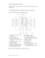
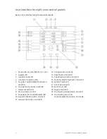
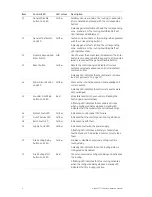
Operator controls and indicators
The following table gives an overview of the control panel operator controls and
indicators. Item numbers refer to Figure 1 on page 3 and Figure 2 on page 4.
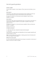
Operational features described here may not be available to all users. Further
information on control panel operation and access restrictions can be found in the
topic “Control panel operation” on page 10.
Table 3: Operator controls and LED indicators
Item Control/LED
LED
colour
Description
1
Zone button and
LEDs
Red/Yellow
Disables or tests a zone (when pressed together with
the general Disable or general Test button).
The red LED indicates an alarm in the corresponding
zone. A flashing red LED indicates that the fire alarm
was activated by a detector. A steady red LED
indicates that the fire alarm was activated by a
manual call point.
The yellow LED indicates a fault, test, or disablement
in the corresponding zone. A flashing yellow LED
indicates a fault. A steady yellow LED indicates that
the zone is disabled or is being tested.
2
Supply LED
Green
Indicates that the system is powered up correctly.
3
General Fault LED
Yellow
Indicates a fault. The corresponding zone, device, or
function fault LED also flashes.
4
General Fire Alarm
LEDs
Red
Indicates a fire alarm.
Flashing LEDs indicate that the fire alarm was
activated by a detector. Steady LEDs indicate that
the fire alarm was activated by a manual call point.
The corresponding zone alarm LED indicates the
source of fire alarm.
5 Sounder
Fault/Disable/ Test
button and LED
Yellow
Disables or tests sounders (when pressed with the
general Disable or general Test button).
A flashing LED indicates a fault with the sounders. A
steady LED indicates that the sounders are disabled
or are being tested.
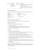
6 Sounder
Delay
button
and LED
Yellow
Enables or disables a previously configured sounder
delay.
A steady LED indicates that a sounder delay is
configured and enabled.
7
Network Fault LED
Yellow
Indicates a network fault.
8
Service Detector LED Yellow
Indicates that a detector requires servicing (CleanMe
compatible detectors only).
9 Expansion
I/O
Fault/Disabled LED
Yellow
Indicates that an installed expansion module has a
fault or is disabled.
A flashing LED indicates a fault with an expansion
module. A steady LED indicates that an expansion
module is disabled.


