– 16 –
Control Panel
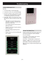
The control panel contains the smart board, the
touchscreen panel, and a three-button circuit
board. Run the test for the control panel (see
Control Performance Test
). The control panel is
replaced as an assembly.
Removal
Remove the hidden vent (see
Microwave Removal
and Component Access
). Remove the grille. Lift up
on the control panel and remove.
Disconnect 8 electrical connectors and the
ground wire from the control panel.
Door Interlock Switches
The oven has 3 interlock switches. All switches
are removed the same.
Door Sensing and Primary Interlock Switches
The primary interlock and monitor switches are
located on the bottom of the plastic switch
bracket. The power relay is mounted on the smart
board. They are activated by the latch heads on
the door. When the door is opened, the switches
interrupt the circuit to all components, except the
oven lamp. A cook cycle cannot take place until
the door is firmly closed, thereby activating both
interlock switches. The primary interlock system
consists of the door sensing switch, primary
interlock switch, and power relay.
Monitor Switch
The monitor switch is operated indirectly by the
bottom latch pawl. The pawl operates a cam
switch, which in turn, activates the monitor
switch. The switch is intended to render the oven
inoperative by means of blowing the monitor fuse
when the contacts of the primary interlock switch
and power relay fail to open when door is opened.
Functions
When the door is opened, the monitor switch
contact closes. At this time, the primary interlock
switch and power relay are in the closed position.
As the door goes to a closed position, the monitor
switch contacts are first opened and then the door
sensing switch and the primary interlock switch
contacts close.The oven has 3 interlock switches.
All switches are removed the same.
Removal
Remove the hidden vent (see
Microwave Removal
and Component Access
). Remove the grill. Lift up
the control panel and remove.
Remove the 2 T20 Torx screws from the front of
the frame and remove the door switch bracket.
Содержание JVM2070 H
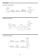
Страница 24: ... 24 Strip Circuits Vent Motor Does Not Work Fan Motor Does Not Work Louver Motor Does Not Work ...
Страница 26: ... 26 Interior Light Does Not Work Surface Lamps Do Not Work ...
Страница 29: ... 29 Code No DE99 00125F WARNING Power must be disconnected before servicing this appliance Schematic ...
Страница 30: ... 30 Illustrated Parts Catalog ...


