background image


Page 35 

Intellix

 BMT 330 User Manual 


BMT330UM 

v1.0 

20-Jun-16 

Bushing Insulation 


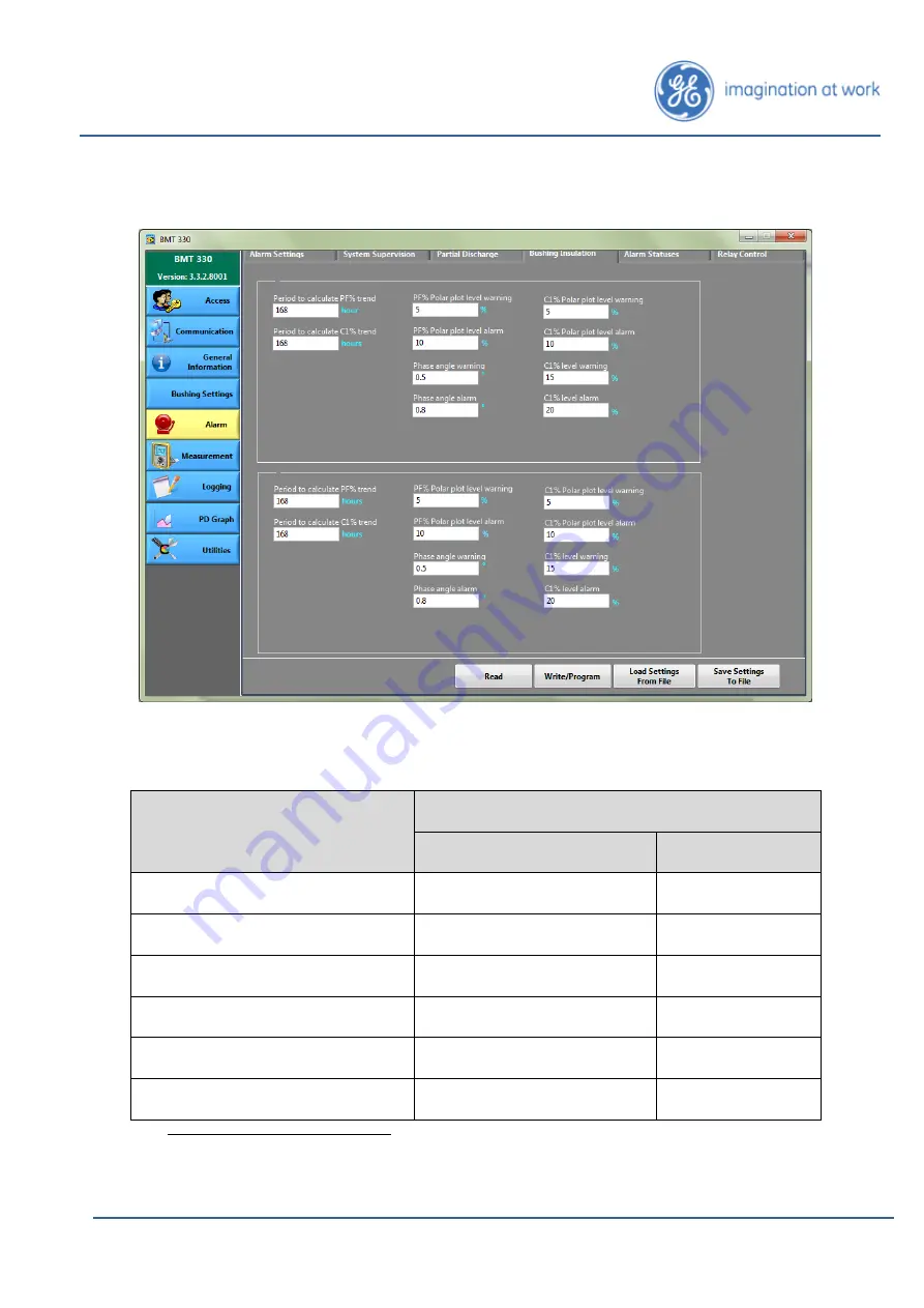
Figure 15: Alarm > Bushing Insulation tab 

 
Enter settings for Primary bushings: 

Parameter 

Suggested Value for both Primary & Secondary

3


Default 

Allowable range

4


Period to calculate PF% trend 

168h 

0 to 720 h 

Period to calculate C1% trend 

168h 

0 to 720 h 

PF% Polar plot level warning 

150% 

0 to 600% 

PF% Polar plot level alarm 

200% 

0 to 600% 

Phase angle warning 

0.5° 

0 to 10° 

Phase angle alarm 

0.8° 

0 to 10° 


3

 Alarm limits and settings must be revised few weeks after installation by customer depending 

on bushing behaviour. 

4

 Value of zero disables this particular alarm. 

Содержание Intellix BMT 330

Страница 1: ...Energy Lissue Industrial Estate East Lissue Road Lisburn BT28 2LU United Kingdom Tel 44 0 28 9262 2915 Fax 44 0 28 9262 2202 E mail ge4service ge com BMT330UM v1 0 20 Jun 16 IntellixTM BMT 330 USER MANUAL ...

Страница 2: ...R LEVEL OPERATIONS WITH IntellixTM BMT 330 12 Connection of PC to Intellix BMT 330 14 Opening the Setup software 15 Changing between Intellix BMT 330 and Intellix BMT 300 units 17 Routine Operations with the Intellix BMT 330 19 Maintenance Operations with the Intellix BMT 330 19 MENU OPERATIONS 20 Communication 20 Notes on Intellix BMT 330 communication ports 23 General Information 25 Device Infor...

Страница 3: ...TS 59 Copyright 2016 General Electric Company Intellix is a registered trademark of General Electric Company This release of this document is accurate at the time of this writing General Electric Company reserves the right to change the Intellix BMT 330 and this document without notice For the latest revision of this manual visit http www gegridsolutions com md catalog BMT330 htm General Electric ...

Страница 4: ...formation 2 Intellix BMT 330 Installation Manual 3 Intellix BMT 330 Service Manual 4 Intellix BMT 330 commissioning instructions 5 Intellix BMT 330 Modbus registers list 6 BMT 330 DNP3 Objects I O Points Index Customer Guide GEDE GA_M DLIS TE CG 049 7 BMT 330 IEC61850 Dataset I O Points Index Customer Guide GEDE GA_M DLIS TE CG 050 ...

Страница 5: ... The Intellix BMT 330 does not require periodic maintenance However if the transformer bushings are replaced by a similar bushing then the Bushing Adaptor circuit integrity checks shall be implemented and the bushing nominal parameters updated before the transformer is returned to service Refer to the Installation manual If the bushing is replaced by a mechanically and or electrically different bu...

Страница 6: ...e PDI Partial Discharge Intensity Warnings Cautions The meaning of symbols used on the Intellix BMT 330 device Refer to the Instruction Manual to prevent injury or damage to equipment Hazardous voltages may be present Primary Protective earth connection This product has been tested to the requirements of CAN CSA C22 2 No 61010 1 third edition or a later version of the same standard incorporating t...

Страница 7: ... injury or death Before performing any manipulation with the Intellix BMT 330 ensure you reviewed all the risk associated with the product listed in this manual and the installation manual Conventions Menu items or options displayed on the display screen are represented in the text in bold for example Alarm Setup Hierarchy is represented by using between the nodes as parent child for example Gener...

Страница 8: ...e 40 to 55 deg C 22 to 131 deg F When equipped with multi master comms option 40 to 55 deg C 22 to 131 deg F Operating Humidity Range 5 to 95 RH non condensing Maximum Operating Altitude 2000m 6500 ft above sea level Storage Temperature Range 40 to 85 deg C 40 to 185 deg F Minimum Ambient Temperature for Installation and Service Activities 20 deg C 4 deg F Cabinet Protection Level IP55 Bushing Sen...

Страница 9: ...3A Type Tests Category Standard Class Level Test EMC Emissions CISPR 11 A Radiated Conducted Emissions FCC part 15 A Radiated Conducted Emissions IEC 61000 3 2 A Harmonic Current Emissions Limits EMC Immunity IEC 61000 4 2 IV Electrostatic Discharge IEC 61000 4 3 III Electro Magnetic Field Immunity IEC 61000 4 4 III Electrical Fast Transients IEC 61000 4 5 III Surge Immunity IEC 61000 4 6 III Cond...

Страница 10: ...tal IEC 60068 2 1 40 C Cold IEC 60068 2 2 55 C Dry Heat IEC 60068 2 6 10 500Hz 1g operation 10 500Hz 1g endurance Vibration IEC 60068 2 30 55 C 95 RH Damp Heat EN 60529 Enclosure IP55 Adaptor IP66 Degree of Protection Safety IEC 61010 1 2010 Corr1 EN 61010 1 2010 UL 61010 1 3rd Edition CSA C22 2 No 61010 1 This product has been tested to the requirements of CAN CSA C22 2 No 61010 1 third edition o...

Страница 11: ...an be done by either a Right click on My Documents from the Start Menu or Desktop select Properties and edit the Target folder location field or b Edit the My Documents registry location directly The key value can be found at HKEY_CURRENT_USER Software Microsoft Windows CurrentVersion Explorer Shell Folders If a manual assignment of the My Documents folder doesn t solve the issue then create a tem...

Страница 12: ... specified by the manufacturer the protection provided by the equipment may be impaired Before starting the configuration confirm that all of the Intellix BMT 330 sensors have been connected All user access activity should take place in ambient temperatures greater than 20 deg C 4 deg F to prevent damage to connectors and cabling as they may become brittle at extreme low temperatures Prior any tes...

Страница 13: ...Page 13 Intellix BMT 330 User Manual BMT330UM v1 0 20 Jun 16 Figure 1 Single Transformer general installation layout Figure 2 Bank of 3 Single Phase Transformers general installation layout ...

Страница 14: ...ocess Ensure that the following steps are followed precisely to avoid the risk of electric shock Prior to accessing the Intellix BMT 330 cabinet de energise any AC supplies to the Intellix BMT 330 Alarm Relay PCB and apply LOTO procedures Open the Intellix BMT 330 cabinet Ground the coaxial inputs by operating the bank of grounding bars available at the DIN rail connectors The mini USB socket on t...

Страница 15: ...ication with the Intellix BMT 330 setup the correct connection and settings and confirm them by pressing the Ping button A Success message must be returned Otherwise go to Communication page 20 Select the Access page and select the required access level from the drop down as appropriate Customer is the default selection Customer requires no password you can navigate around the side tabs immediatel...

Страница 16: ...sformer Bushing Settings page 28 This allows the entry of the basic modelling parameters Alarm page 29 This gives allows entry of the alarm thresholds and gives access to and reset of the current alarm status Measurement page 47 This displays the current values of the monitored parameters Logging page 49 This configures the rate at which data is logged to SD card and allows manual download of the ...

Страница 17: ... Software is unable to establish an automatic connection on opening it will default to the Intellix BMT 330 interface To subsequently connect to an Intellix BMT 300 unit the communications settings need to be setup and a Ping Communication page will return a message stating that the firmware does not match the 3 3 version of the BMT Setup Software This message indicates that a successful firmware ...

Страница 18: ...n BMT Setup Software Check Firmware version using last connection settings Open 330 Monitor App Open 300 Monitor App Open 330 Monitor App Change Communication Settings Ping message of firmware app mismatch Close application Confirmed BMT 300 Firmware Confirmed BMT 330 Firmware Unknown Firmware or No Connection ...

Страница 19: ...ings Acknowledge alarms go to page 37 for the Alarm Statuses Change alarm thresholds go to page 29 for the Alarm Settings View the instantaneous readings of Intellix BMT 330 parameters go to page 47 Clear or download the logged data go to page 50 Maintenance Operations with the Intellix BMT 330 Whenever the bushings are serviced the Bushing Adaptor connections must be checked for continuity and pr...

Страница 20: ... the low speed of the connection Note 2 The settings in the Communication page are used to ensure that the BMT 330 Setup Software is attempting the communication with the correct protocol settings If it is required that the Modbus protocol settings on the Intellix BMT 330 are to be changed then refer to the Utilities section on page 55 If you change the Utilities Modbus Slave Settings then you wil...

Страница 21: ...commands see below of the modem driver s interface To validate the Communication settings click the Ping button Once the settings are confirmed it is suggested that they are saved for future reference by pressing the Save Setting to File button A Windows File Dialogue will open to allow you to name the settings file in configuration cfg format and set the save location as shown in Figure 7 below N...

Страница 22: ...ded in Utilities Terminal or alternatively use a third party terminal application such as Hyperterminal Note that Hyperterminal is no longer installed by default with Windows 7 or later Windows OS but it can be freely downloaded If using a third party terminal configure it as baud 115200 8 data bits No parity 1 stop bit and Flow Control none Click on Get Modbus Settings or enter the command mbs Yo...

Страница 23: ...ithout filtering 6 both hardware bi directional and software bi directional flow control with filtering NOTE The AT commands above and flow control modes are widely accepted as standard but may differ for a particular modem Please refer to the modem documentation Notes on Intellix BMT 330 communication ports Two ports PORTØ and PORT1 are available in Intellix BMT 330 see Figure 8 Both ports can be...

Страница 24: ... master However the downloading of historical data from the Intellix BMT 330 requires a direct connection to Intellix BMT 330 via a transparent channel MODBUS RTU also provided by the optional Kalkitech module This transparent channel is a single master communication port Simultaneous and independent use of 1 the multi master MODBUS TCP DNP3 0 or IEC61850 interface and 2 single master direct conne...

Страница 25: ...g 32 extended ASCII characters Enter a meaningful name to identify the device Time zone Define the GMT time zone with this drop down menu NOTE internal time is UTC Perception uses the Time Zone modifier to adjust for local time The button functions are Sync Time synchronises the Intellix BMT 330 time to the PC time Read read the current Intellix BMT 330 settings into the application Write Program ...

Страница 26: ...unit must be selected from the associated drop down menu Transformer Rated secondary voltage enter the nominal line to line voltage kV Used to calculate ILV ref Neutral type select from drop down menu with 2 options available not available If available PD polarity discrimination is made available in System Configuration refer to the companion Intellix BMT 330 Service Manual Power System frequency ...

Страница 27: ...Once all the settings have been entered press the Write Program button to load the settings into the Intellix BMT 330 It is advisable to save the configuration file by pressing the Save Settings To File button Figure 10 General Information Transformer Rating tab ...

Страница 28: ...le inputs e g TR1 HV Enter phase labels e g U V and W Select what bushing is associated to each input Finally select what temperature is associated to each input for the bank of 3 single phase transformers case The expected currents and inter phase angles are then displayed in this tab as per the selected bushings Once the inputs have been configured press the Write Program button to load the sett...

Страница 29: ... are set to manual acknowledgement in the Alarm Settings tab then alarms have to be manually acknowledged and reset in this tab Relay Control go to page 46 Please note that the default alarm values for PD and bushing monitoring are conservative and therefore may be tight for some transformers These alarm values should be reviewed when the transformer is energised and again 1 month after Intellix B...

Страница 30: ... see below Once the trigger is armed it will not be disarmed until this particular parameter is below its hysteresis corrected threshold see above If the Alarm Status is Auto the alarm will switch off if the trigger is disarmed If it is Manual the alarm will be on independently of the trigger status until it is acknowledge at which time the alarm will switch off if the trigger is unarmed Alarm tre...

Страница 31: ...s the alarm trigger value Default 75 deg C usual operating range 40 to 70 deg C Field devices comm error Number of continuous failed comms attempts before triggering alarm Default 50 Inter CPU comm error Number of continuous failed comms attempts before attempting to recover the inter CPU communication If unsuccessful the alarm will be triggered Default 100 Neutral CT failure timeout Period with P...

Страница 32: ... Percentage change in nominal frequency which triggers an alarm default 2 Modbus comm error Number of continuous errors in the internal RS485 line which triggers an alarm default 50 No Signal Warning Default 10 The percentage of Iref below which this alarm is triggered Bushing R Failure Warning The percentage increase in bushing adaptor sampling current from one sampling period to the next that tr...

Страница 33: ...720 High noise level high 0 disabled 0 to 100 PD max level warning 8000 pC 0 to 65000 PD max level alarm 12000 pC 0 to 65000 PD average level warning 1000 pC 0 to 65000 PD average level alarm 2000 pC 0 to 65000 PD average level trend warning 0 disabled 0 to 65000 1 Alarm limits and settings must be revised a few weeks after installation by customer depending on bushing behaviour 2 Value of zero di...

Страница 34: ...to 65000 PD count level warning 0 disabled 0 to 65000 PD count level alarm 0 disabled 0 to 65000 PD count trend warning 0 disabled 0 to 65000 PD count trend alarm 0 disabled 0 to 65000 PDI level warning 1000 mW 0 to 65000 PDI level alarm 2000 mW 0 to 65000 PDI trend warning 0 disabled 0 to 65000 PDI trend alarm 0 disabled 0 to 65000 Table 4 Partial Discharge Alarm Settings ...

Страница 35: ...ult Allowable range4 Period to calculate PF trend 168h 0 to 720 h Period to calculate C1 trend 168h 0 to 720 h PF Polar plot level warning 150 0 to 600 PF Polar plot level alarm 200 0 to 600 Phase angle warning 0 5 0 to 10 Phase angle alarm 0 8 0 to 10 3 Alarm limits and settings must be revised few weeks after installation by customer depending on bushing behaviour 4 Value of zero disables this p...

Страница 36: ... 10 0 to 100 C1 level warning 15 0 to 100 C1 level alarm 20 0 to 100 Table 5 Bushing Insulation Alarm Settings After entering settings for Primary bushings repeat procedure and enter settings for Secondary bushings if applicable Write the alarm settings to the Intellix BMT 330 by pressing the Write Program button It is advisable to save the configuration file by pressing the Save Settings To File ...

Страница 37: ...Status refreshes the alarm status screen Acknowledge Acknowledges the selected alarms but leaves them at their current status as given by the alarm trigger state see Alarm Settings Service alarms The following events will trigger a service alarm Service Alarm Description High CommCPU Temperature Comm CPU temperature is above the given threshold see High Comm CPU temperature in Table 3 High FPGA Te...

Страница 38: ...e Communication Error Intellix BMT 330 cannot communicate with the door mounted LED board see Field devices comm error in Table 3 InterCPU CAN Device Error Communication between the 2 Intellix BMT 330 CPUs cannot be established see Inter CPU comm error in Table 3 Rejected Phase Packet Error Bushing monitoring data could not be delivered from the FPGA to the main CPU see Rejected phase packet in Ta...

Страница 39: ... Table 3 Neutral CT Failure Warning Whilst PD events have been detected by the Primary input no PD event has been picked up by the Neutral CT A for a given period of time see Neutral CT failure timeout in Table 3 GPS Signal Error Status No signal is being received from the GPS SD Card Error Status Read write operations with the internal SD card fail Neutral CT 2 Failure Warning Status Whilst PD ev...

Страница 40: ...vices comm error in Table 3 Top Oil Device 4 Communication Error Status Intellix BMT 330 cannot communicate with the Top Oil 4 magnetically mounted temperature sensor see Field devices comm error in Table 3 Primary A Current Saturation Primary A input is saturated see Bushing current saturation limit in Table 3 Primary B Current Saturation Primary B input is saturated see Bushing current saturatio...

Страница 41: ...PD average level alarm in Table 4 Primary Phase C PD Average Polar Plot Level Status The PD apparent charge for Primary C in the polar plot is above a given threshold see PD average level warning and PD average level alarm in Table 4 Primary Phase A PD Average Polar Plot Trend Status The PD apparent charge change for Primary A in the polar plot is above a given threshold see Period to calculate PD...

Страница 42: ...end Status The PD count change for Primary B in the polar plot is above a given threshold see Period to calculate PD trend PD count trend warning and PD count trend alarm in Table 4 Primary Phase C PD Count Polar Plot Trend Status The PD count change for Primary C in the polar plot is above a given threshold see Period to calculate PD trend PD count trend warning and PD count trend alarm in Table ...

Страница 43: ... area defined by Primary A see C1 Polar plot level warning and C1 Polar plot level alarm in Table 5 Primary Phase B C1 Polar Plot Level Status The C1 polar plot amplitude is above a given threshold on an area defined by Primary B see C1 Polar plot level warning and C1 Polar plot level alarm in Table 5 Primary Phase C C1 Polar Plot Level Status The C1 polar plot amplitude is above a given threshold...

Страница 44: ...nput current has changed beyond a given threshold see C1 level warning and C1 level alarm in Table 5 Secondary Phase B C1 Level Status The Secondary B measured input current has changed beyond a given threshold see C1 level warning and C1 level alarm in Table 5 Secondary Phase C C1 Level Status The Secondary B measured input current has changed beyond a given threshold see C1 level warning and C1 ...

Страница 45: ... Secondary C see PF Polar plot level warning and PF Polar plot level alarm in Table 5 Primary Angle AB The measured inter phase angle between Primary A and B is beyond a given threshold respect the expected angle see Phase angle warning and Phase angle alarm in Table 5 Primary Angle AC The measured inter phase angle between Primary A and C is beyond a given threshold respect the expected angle see...

Страница 46: ...rning and Relay 3 Alarm are de energized by default If either of their respective alarms is on the corresponding relay will switch to ON Relays can be manually controlled by disabling the Active relay on alarm Then the relays are not synchronized with the alarm statuses and the user can manually switch the relays by clicking on the relay switch icon and then click on Write Program NOTE disabling t...

Страница 47: ... Pressing the Stop button will cease polling The Clear Error button resets the Last detected error and the Measurement Sensors Field Sensors Error counters The Measurement page holds 2 tabs Measurements p 47 that displays the bushing monitor and PD values and Sensors p 48 that displays the CANBUS sensors and GPS Measurements Figure 18 Measurements tab Note The C1 measurements are calculated based ...

Страница 48: ...The PD Max displayed on this page is the maximum PD value for the cycle The log file PD Max is the maximum value of the PD averaged over each cycle This PD Max is refreshed every 2 seconds PD pC is the amplitude apparent charge of the PD event PD count is the number of partial discharge events per cycle PDI mW is the average power associated to a PD event as defined in IEC 60270 Sensors Figure 19 ...

Страница 49: ...ging The Logging page has 2 tabs Log Settings go to page 49 Log Data go to page 50 Log Settings Figure 20 Logging Log Settings tab Parameter Suggested Value or Source of Data Log Enable Checked Enabled Log Interval The period between log recordings Default is 1 hour ...

Страница 50: ...ntries to the Intellix BMT 330 by pressing the Write Program button It is advisable to save the configuration file by pressing the Save Settings To File button Log Data Figure 21 Logging Log Data tab Log File enter or browse to a location to store log files Log Type Select from the drop down whether you require a measurement status or the extended PRPD PD log file The file grid is populated with t...

Страница 51: ...the log file selected by the log file browser below o Download Complete log If Download complete log is checked then the full selected log will be downloaded but for the registers set by the Skip first checkbox o Latest records If Download latest records is checked then only the latest record will be downloaded If 48 records is set in this field and the Log Interval is set to 1 hours then the last...

Страница 52: ...ure 22 PD Graph page By default the last recorded PRPD for the selected input to right corner is displayed A reference sinusoidal can be shown hidden by presing on the Reference Wave button and its colour selected on the colour palette on its right The PRPD can be exported as an image by pressing on the Export Image button The PRPD display can be modified by using the provided controls Removes any...

Страница 53: ...le and to format the axis labels If you right click whilst the cursor is within the graph area a pop up menu appears as shown in Figure 23 Figure 23 PRPD graph pop up menu The options allow the following Copy Data stores an image copy of the PRPD into the clipboard so that it can be pasted into other applications Description and Tip shows the description and tip for this PRPD Currently these value...

Страница 54: ...M v1 0 20 Jun 16 AutoScale Autoscales the selected axis Smooth Updates Makes graphic PRPD transitions visually smoother e g when zooming in The Export option allows to export the PRPD to the clipboard an excel spreadsheet or as a simplified image ...

Страница 55: ...t rate Protocol Either binary RTU or text ASCII Parity extra bit used for error checking EVEN ODD NONE The parameters above can take any value as long as they match the ones in the Communication page Also if there are other layers between the PC application and Intellix BMT 330 these layers must be able to handle the port settings and then the matching must be The Communication Settings must match...

Страница 56: ...o a file but not load them from a file First ensure that the BMT 330 Setup Software is synchronised to the values in the Intellix BMT 330 by left click the Read Settings from Device button Then enter a file name and path in the setting file box or select a path and a file using the Save As dialog that is open by a left click on the yellow folder and press the Save button ...

Страница 57: ...lable in the cabinet as shown in Figure 27 Select the COM port assigned to it by the PC and press Get Modbus Settings 5 Press Reset Modbus Settings to reset the ports settings to their default values see Communication p 20 Figure 27 Location of secondary mini USB port 5 The assigned COM port can be found by right clicking Computer and selecting Manage followed by selecting Device Manager under Por...

Страница 58: ...ine the PC restart opt for restart later Install the Visa suite o Open the Intellix BMT 330 Prereqisities directory o Open the Volume directory o Double click on the setup exe o After the installation decline the PC restart opt for restart later Install the USB to Serial driver o Open the Intellix BMT 330 Prereqisities directory o Open the USB to 232 directory o Double click on the PL2303_Prolific...

Страница 59: ...T PANEL LIGHTS Light Colour Light Symbol Meaning GREEN AC power applied BLUE Service Required Triggered by warning service event YELLOW A measured parameter has exceeded a user programmed warning threshold RED A measured parameter has exceeded a user programmed alarm threshold ...

Отзывы: