


GE M
EDICAL
S
YSTEMS
D
IRECTION
2392751-100, R
EVISION
3
V
IVID
™ 4 S
ERVICE
M
ANUAL
8-132
Section 8-8 - Peripherals
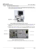
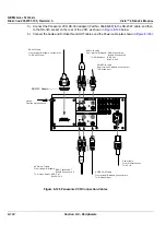
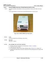
3.) Connect the Panasonic VCR RS-323 adaptor (Part No. 066E8200) to the RS-232C cable, and then
to the RS-323 socket on the rear of the VCR, as shown in
4.) Connect the Audio and S-Video IN and OUT cables, and the Power cable (also shown in
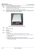
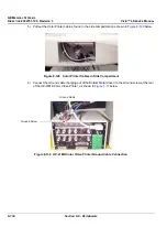
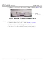
Figure 8-126 Panasonic VCR Connection Cables
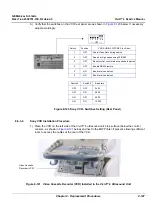
S-VIDEO IN cable
From: Internal IO Module, Connector A11
To: S-Video Input
S-VIDEO OUT cable
From: Internal IO Module, Connector A10
To: S-Video Output
Power cable
From: Distribution box
To: AC IN
AUDIO IN cable
From: Internal IO Module:
To: S-Video Input:
RED: Connector A9
BLACK: Connector A8
RED: CH1
BLACK: CH2
AUDIO OUT cable
From: Internal IO Module:
To: S-Video Output:
RED: Connector A7
BLACK: Connector A6
RED: CH1
BLACK: CH2
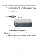
RS-232C cable
From: Internal IO Module, Connector A2
To: RS-232C Input
Ground:
From the system chassis
D
E
R
K
C
A
L
B
D
E
R
K
C
A
L
B
RS-232C Adaptor


