


GE M
EDICAL
S
YSTEMS
D
IRECTION
2392751-100, R
EVISION
3
V
IVID
™ 4 S
ERVICE
M
ANUAL
8-86
Section 8-6 - Lower Section Components Replacement
8-6-2
AC Input Box Replacement Procedure
8-6-2-1
Tools
Use the appropriate flat and Phillips-type screw drivers and a wire cutter as indicated in the AC Input
Box replacement procedure.
8-6-2-2
Preparation
Shut down the Vivid™ 4 ultrasound unit, as described in
.
8-6-2-3
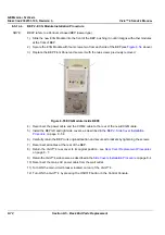
AC Input Box Removal Procedure
1) Unplug the AC line power cable.
2) Remove the Vivid™ 4 left, right and rear covers, as described in the
3) Unplug the internal power cable from the AC Distribution Box.
4) Unscrew the Ground cable from the AC Distribution Box.
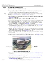
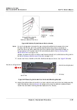
5) Remove the two screws on both the
left
and the
right
sides that secure the AC Input Box to the
chassis.
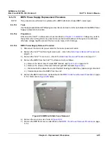
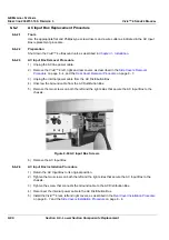
Figure 8-69 AC Input Box Screws
6) Remove the AC Input Box.
8-6-2-4
AC Input Box Installation Procedure
1) Return the AC Input Box to its original position.
2) Tighten the two screws on both the
left
and the
right
sides that secure the AC Input Box to the
chassis.
3) Tighten the screw that connects the Ground cable to the AC Distribution Box.
4) Reconnect the internal power cable to the AC Distribution Box.
5) Install the Vivid™ 4 rear, left and right covers, as described in the
Rear Cover Installation Procedure
on page 8 - 7 and the


