GE Appliances & Lighting
Technical Service Guide
October 2014
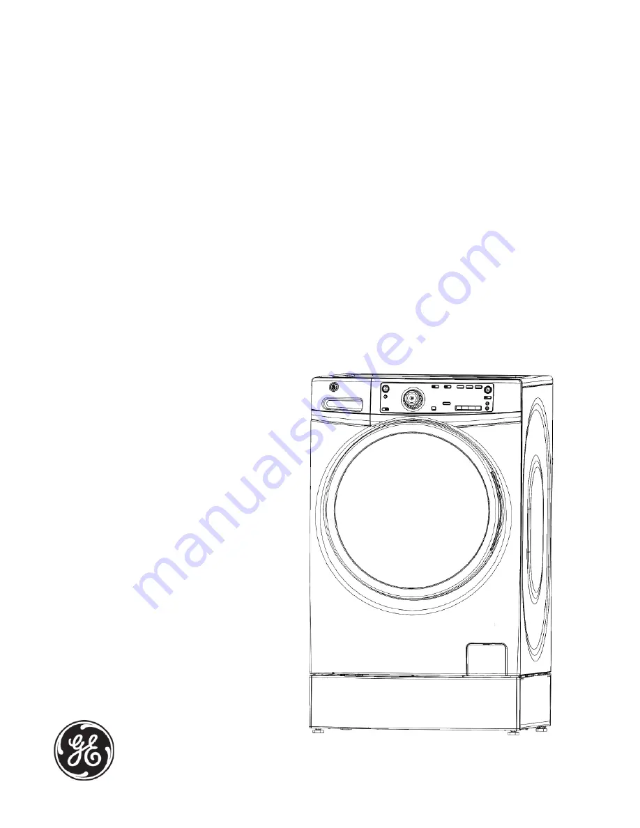
Louisville Built Front Load Washer
GFWS2500/GFWS2505
GFWS2600/GFWS2605
GHWS3600/GHWS3605
GFWS3700/GFWS3705
GFWR4800/GFWR4805
31-9236
GE Appliances & Lighting
General Electric Company
Louisville, Kentucky 40225